D9412GV4/D7412GV4 v2.03 | Installation and System Reference Guide | 10.0 Off-Board Outputs
.
Bosch Security Systems, Inc. | 7/16 | F01U265457-09 62
10.1.1 Configuring the D8129 OctoRelay
Five switches on the OctoRelay determine the
relay numbers for the eight relay outputs
(Table 19).
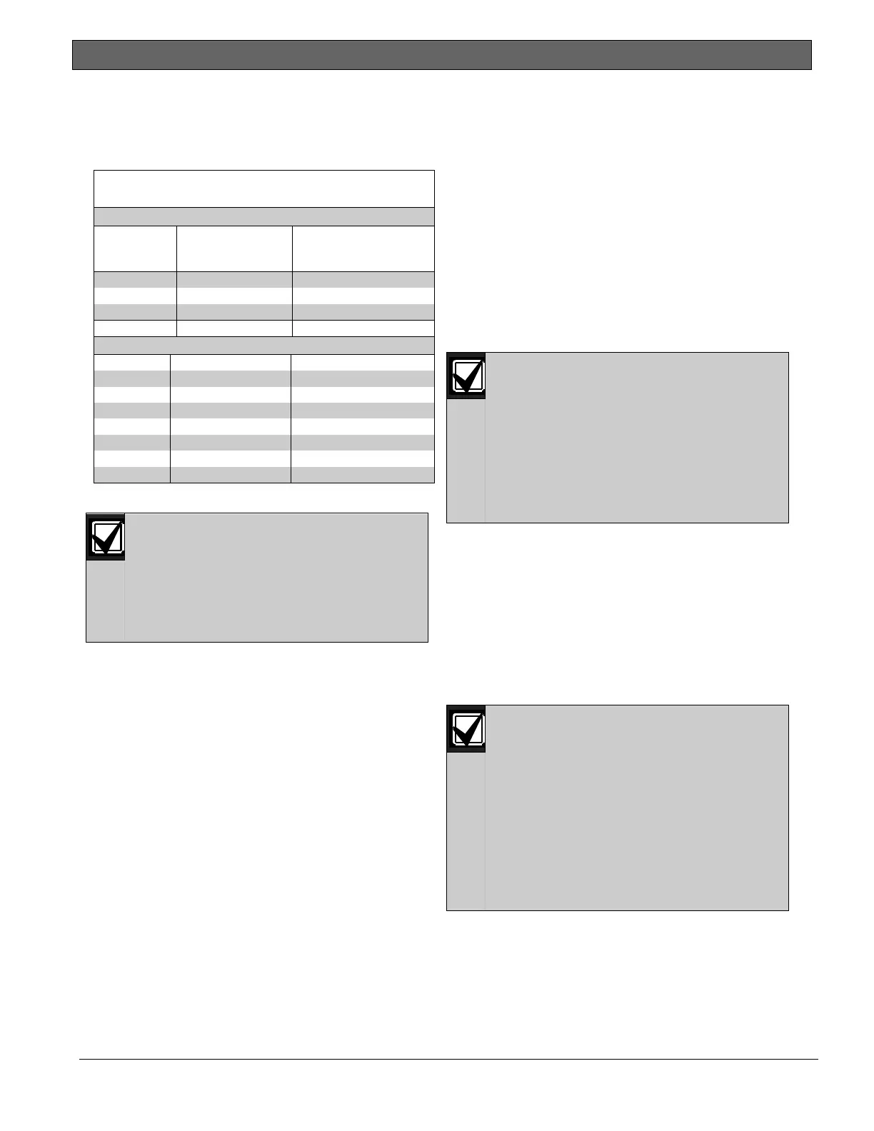
Table 19: D8129 OctoRelay Switch Settings
Panel
Relay
Number
D8129 OctoRelay
Switch Setting
On Panel, Connect
D8129 to:
1 to 8 Off-On-On-On-On Zonex 1 Terminal 28
9 to 16 On-Off-On-On-On Zonex 1 Terminal 28
17 to 24 Off-Off-On-On-On Zonex 1 Terminal 28
D7412G Maximum
65 to 72 Off-On-On-On-On Zonex 2 Terminal 26
73 to 80 On-Off-On-On-On Zonex 2 Terminal 26
81 to 88 Off-Off-On-On-On Zonex 2 Terminal 26
89 to 96 On-On-Off-On-On Zonex 2 Terminal 26
97 to 104 Off-On-Off-On-On Zonex 2 Terminal 26
105 to 112 On-Off-Off-On-On Zonex 2 Terminal 26
113 to 120 Off-Off-Off-On-On Zonex 2 Terminal 26
121 to 128 On-On-On-Off-On Zonex 2 Terminal 26
10.1.2 Relay Outputs
Relay outputs can activate when you
are setting the OctoRelay switches or
programming the control panel.
Disconnect equipment connected to
relay outputs when you perform these
functions.
Each OctoRelay output provides a Form C dry
contact rated for 1.0 A at 12.0 VDC. Normally-
open, common, and normally-closed terminals are
available for each relay output. When an
individual output is activated, continuity exists
between the normally-open and common
terminals. When the output is not activated,
continuity exists between the normally-closed
and common terminals.
10.1.3 Installation
Set the switches on the OctoRelay before
installing it in the enclosure. Refer to Section
10.1.1 Configuring the D8129 OctoRelay.
Install the OctoRelay in the enclosure with the
control panel (Figure 2 on page 11) or in an
adjacent enclosure that is no more than 5 ft (1.5
m) from the control panel. Use 16 AWG (1.5 mm)
to 22 AWG (0.8 mm) wire.
To install OctoRelays in the enclosure with the
control panel:
1. Align the module with one of the mounting
locations in the enclosure (refer to Figure 2
on page 11).
2. Using the screws provided with the module,
secure the module in the enclosure.
Use the D137 Mounting Bracket or D9002
Mounting Skirt to install OctoRelays in
enclosures with no available module
mounting locations.
10.1.4 Wiring Connections
Power down the control panel to connect
OctoRelays. Refer to Figure 22 or Error!
Reference source not found. on page 61.
OctoRelays for Relays 1 to 24 connect
to Zonex 1.
OctoRelays for Relays 1 to 64 connect
to Zonex 1, Terminal 28 on the
D7412GV4 only.
OctoRelays for Relays 65 to 128
connect to Zonex 2, Terminal 26 on
the D9412GV4 only.
Only one OctoRelay is shown wired to each
Zonex bus in Figure 22 on page 61. Wire
additional OctoRelays in parallel. Review Section
6.0 Power Outputs on page 34 for information
about providing enough power for the relays.
The number of D8129 OctoRelays that can be
connected to each Zonex terminal on the
D9412GV4 control panels is limited by the
number of D8128D OctoPOPITs connected.
Using D8129 OctoRelays and D8128D
OctoPOPITs together on the same
Zonex terminals is limited and
depends on the number of D8128
OctoPOPITs and D8129 OctoRelays
connected to a single Zonex Bus.
Refer to Table 20 for information
about the maximum number of
D8128Ds and D8129s you can connect
to a single Zonex bus.

 Loading...


