EasyManuals Logo

Bosch D9412GV4 Installation And System Reference Guide

Bosch D9412GV4
170 pages
To Next Page IconTo Next Page
To Previous Page IconTo Previous Page
Page #82 background imageLoading...
Page #82 background image
D9412GV4/D7412GV4 v2.03 | Installation and System Reference Guide | 15.0 Faceplates
.
Bosch Security Systems, Inc. | 7/16 | F01U265457-09 82
15.0 Faceplates
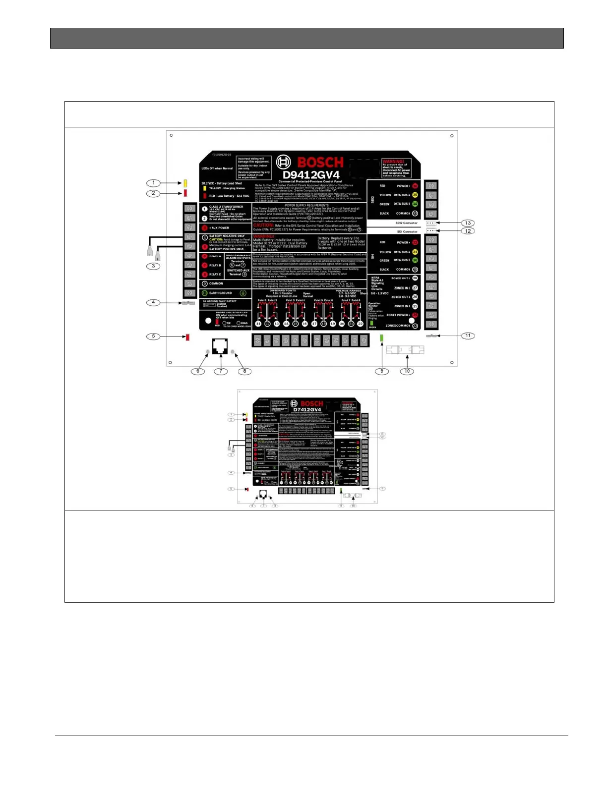
15.1 D9412GV4/D7412GV4 v2.00 (and higher) Faceplate
Figure 38: D9412GV4/D7412GV4 v2.00 (and higher) Faceplate
1 - Charging status LED (yellow)
2 - Low battery LED (red)
3 - Color-coded battery leads
4 - Ground fault detect enable
5- Phone LED (red)
6 - Tip
7 - Telephone cord connector
8 - Ring
9 - Operation monitor LED (green)
10 - Accessory connector
11 - Reset pin
12 - SDI interconnect wiring connector
13 - SDI2 interconnect wiring connector

Table of Contents

Other manuals for Bosch D9412GV4

Questions and Answers:

Question and Answer IconNeed help?

Do you have a question about the Bosch D9412GV4 and is the answer not in the manual?

Bosch D9412GV4 Specifications

General IconGeneral
Power Supply12 VDC
TypeControl Panel
ModelD9412GV4
ManufacturerBosch
Operating Temperature0°C to +49°C (+32°F to +120°F)
Compatible withConettix IP, GSM, GPRS, and POTS communicators

Related product manuals