D9412GV4/D7412GV4 v2.03 | Installation and System Reference Guide | 13.0 SDI2 Devices
.
Bosch Security Systems, Inc. | 7/16 | F01U265457-09 77
receiver. Supervision ensures reliable
operation between the module and the control
panel.
If supervised and the module does not respond
to control panel supervision polls, then a
system fault message appears at the keypads.
A corresponding report is sent to the central
station.
13.7.2 Local RPS Programming
Use the B420’s IP Direct connect feature to
locally connect with RPS. This connection
method requires a direct IP connection from
the PC to the B420’s Ethernet port, which
requires you to remove the Ethernet cable that
connects the B420 to the Web for the duration
of the IP direct connection. Be sure to
reconnect the B420 to the internet when you
finish.
The IP Direct connection for RPS uses the
B420’s AutoIP configuration. Refer to the B420
Installation and Operation Guide for
configuration information. This connection
method also allows diagnostic and history
retrieval.
13.7.3 Ethernet Communications Module
Faults
With a B420 Ethernet Communications Module
installed, several services are made available to
D9412GV4/D7412GV4 v2.03 control panels.
Any break in the Ethernet connection to a
supervised B420 results in a system fault at the
keypads indicating Open Cable trouble. An SDI
FAULT event is sent to central station, if
enabled.
If a Domain Name Server (DNS) is available on
the network, a failure to resolve an individual
Network Address host name results in a system
fault at the keypads indicating DNS ERROR ##.
The error number represents the
communication module and path destination
combination that failed. Refer to the CONTROL
PANELS (D9412GV4/D7412GV4 V2.03) Program
Entry Guide for details on communication
module/path destination combinations. A
failure to resolve the domain name used for
RPS Network Address is displayed on the
keypads as DNS ERROR 99.
If a B420 fails all communication with the DNS,
a system fault indicating Network Module #
Address Error will be displayed on all keypads
and a SDI TROUBLE event is sent to the central
stations, if enabled.
13.8 B520 Auxiliary Power Supply
Module
The B520 Auxiliary Power Supply Module is an
auxiliary power supply module that provides
the ability to expand power requirements via
an SDI2 compatible system by directly
connecting to an SDI2 device bus, or other 12
volt devices. The B520 is fully supervised. This
module provides auxiliary power to SDI2
modules, or other 12 volt devices which are
connected to a compatible control panel. You
can add up to eight B520 modules to a control
panel.
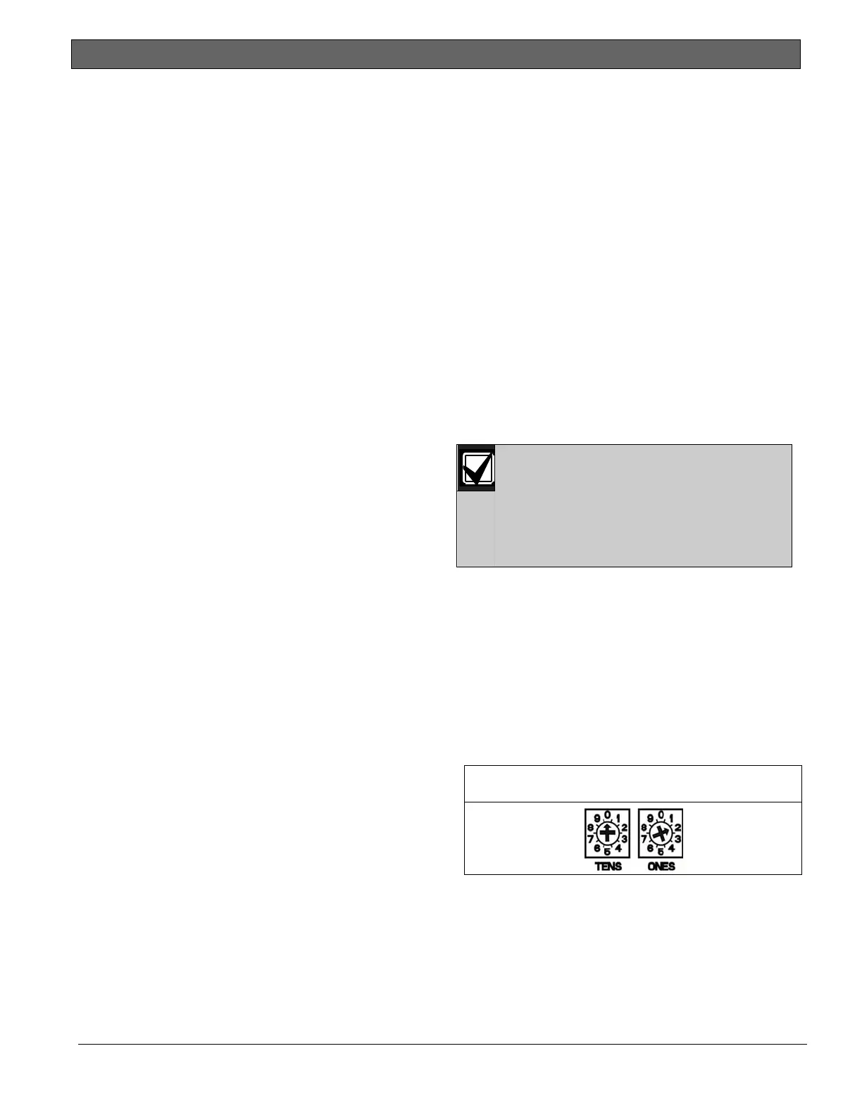
13.8.1 Address Settings
The control panel reads rotary switch
setting changes on power up. If you
change the switches after installation
and applying power to the control
panel, you must recycle the power to
the control panel.
Valid B520 address switches determine the
internal address of the device. The address
switch range for the B520 on a
D9412GV4/D7412GV4 v2.03 Control Panel is 1
through 8. Addresses 00 and 09 through 99 are
not permissible on the SDI2 device bus. Refer
to Figure 34 and Table 30 for valid switch
setting addresses.
If you set the switch to an invalid address, the
B520 reports as missing.
Figure 34: B520 Switch Set to Address 2

 Loading...


