D9412GV4/D7412GV4 v2.03 | Installation and System Reference Guide | 13.0 SDI2 Devices
.
Bosch Security Systems, Inc. | 7/16 | F01U265457-09 76
13.6.3 Local RPS Programming
Use the B426’s IP Direct connect feature to
locally connect with RPS. This connection
method requires a direct IP connection from
the PC to the B426’s Ethernet port, which
requires you to remove the Ethernet cable that
connects the B426 to the Web for the duration
of the IP direct connection. Be sure to
reconnect the B426 to the internet when you
finish.
The IP Direct connection for RPS uses the
B426’s AutoIP configuration. Refer to the B426
Installation and Operation Guide for
configuration information. This connection
method also allows diagnostic and history
retrieval.
13.6.4 Ethernet Communications Module
Faults
With a B426 Ethernet Communications Module
installed, several services are made available to
D9412GV4/D7412GV4 v2.03 control panels.
Any break in the Ethernet connection to a
supervised B426 results in a system fault at the
keypads indicating Open Cable trouble. An SDI
FAULT event is sent to the central station, if
enabled.
If a Domain Name Server (DNS) is available on
the network, a failure to resolve an individual
Network Address host name results in a system
fault at the keypads indicating DNS ERROR ##.
The error number represents the
communication module and path destination
combination that failed. Refer to the CONTROL
PANELS (D9412GV4/D7412GV4 V2.03) Program
Entry Guide for details on communication
module/path destination combinations. A
failure to resolve the domain name used for
RPS Network Address is displayed on the
keypads as DNS ERROR 99.
If a B426 fails all communication with the DNS,
a system fault indicating Network Module #
Address Error will be displayed on all keypads
and a SDI TROUBLE event is sent to the central
stations, if the report has been enabled.
13.7 B420 Ethernet Communication
Module
B420 Ethernet Communication Modules are
four-wire powered SDI2 devices that provide
connection for two-way communication over
Ethernet networks to the control panels. You
can add up to two B420 Ethernet
Communication Modules.
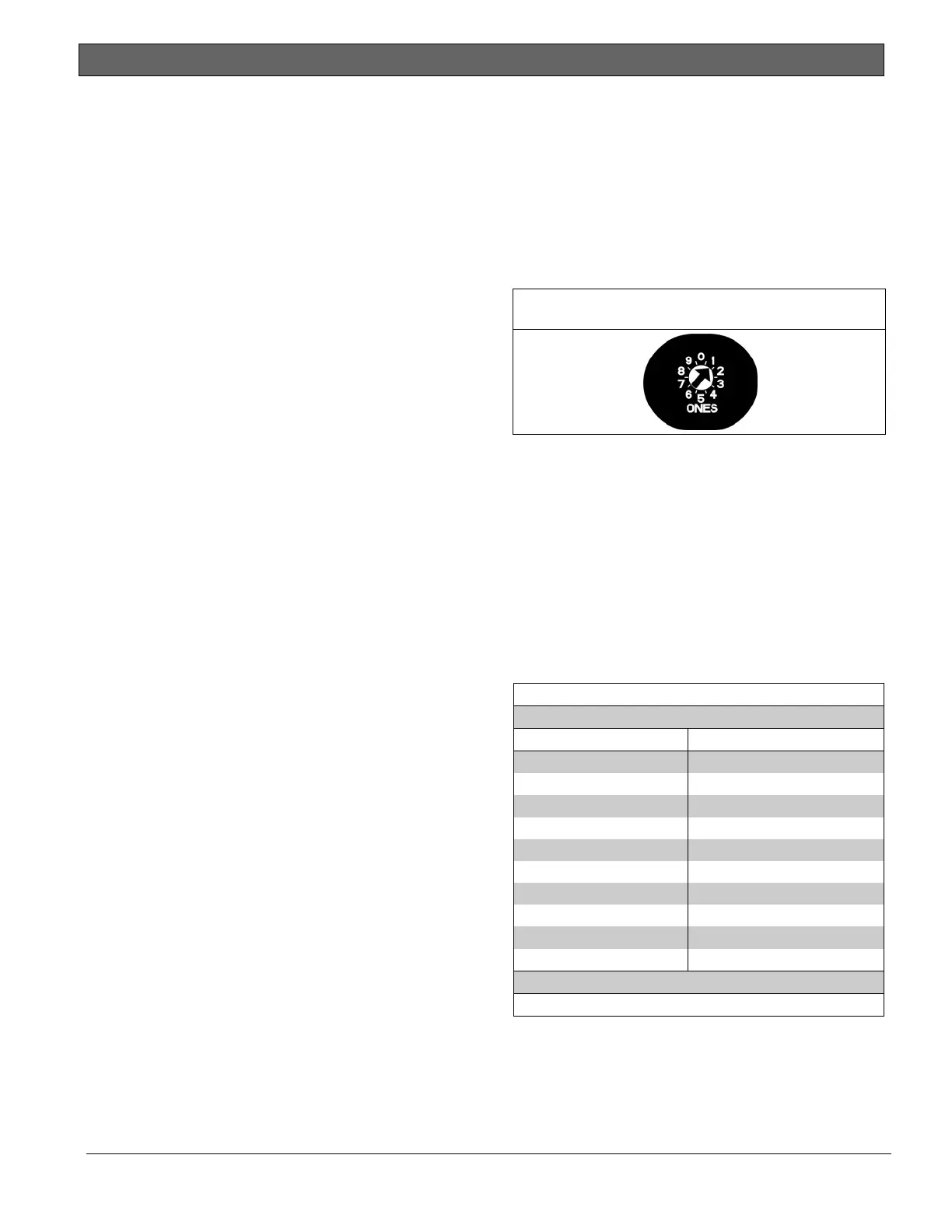
13.7.1 Address and Emulation Settings
The B420 address switches provide a single-
digit setting for the module’s address. The
module uses addresses 0 through 9. Refer to
Figure 33.
Figure 33: B420 Switch Set to Address 1
The B420 has specific rotary switch settings
for SDI Addresses 88 and 92 or SDI2
Addresses 1 and 2 when used to communicate
with Remote Programming Software (RPS) or
with a central station network receiver. Refer
to Table 29 for the correct switch settings.
When the Reset Pin (labeled S1) is closed, all
SDI communication module addresses are
automatically enabled for RPS communication
without restriction.
Table 29: B420 Address and Emulation Settings
Rotary Switch Setting Bus Type and Setting
0 Default
1 SDI2 – Address 1
2 SDI2 – Address 2
3* SDI – Address 80
4* SDI – Address 88
5* SDI – Address 92
6* N/A for GV4
7* N/A for GV4
8* N/A for GV4
9* N/A for GV4
*
Emulates DX4020 operation.
13.7.2 Supervision
Supervision of Ethernet Communication
Modules at SDI2 Addresses 1 and 2 are
enabled automatically when used to
communicate with a central station network

 Loading...


