D9412GV4/D7412GV4 v2.03 | Installation and System Reference Guide | 4.0 Installation
.
Bosch Security Systems, Inc. | 7/16 | F01U265457-09 22
Table 7: Ground Fault Impedance
Specifications
Impedance
Control Panel Detects Ground
Fault
≤ 300 Ω Yes
300 Ω to
200 k Ω
Detection depends upon the
terminal
≥ 200 k Ω No
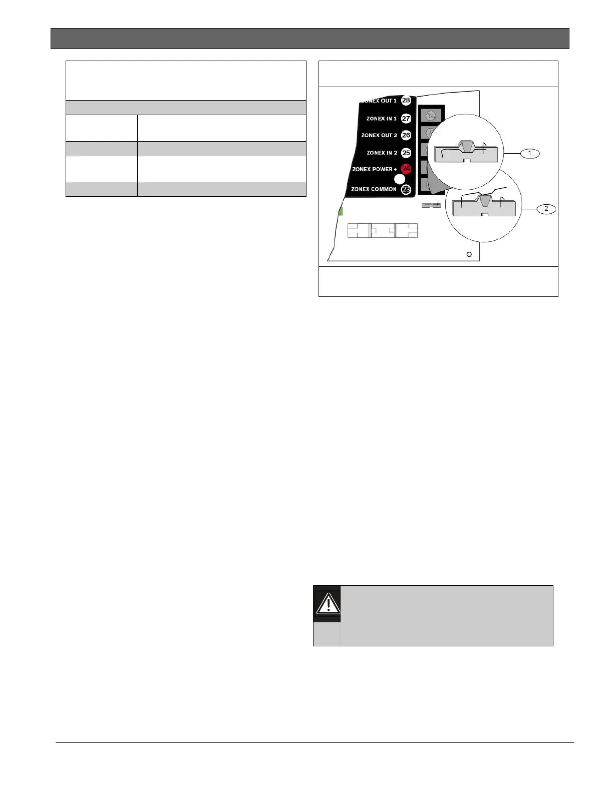
4.5.5 Locking the Reset Pin
Locking the reset pin disables the control panel
(Figure 4). When the control panel is disabled,
the system ignores most keypad commands and
points. Call for Service appears in some keypad
displays when the pin is locked down. SDI2
keypads display “Installation Passcode” when the
pin is locked down.
On-board outputs (Terminals 6 and 7) and off-
board outputs deactivate when the control panel
is reset. Terminal 8 has power when the output is
deactivated. Activation interrupts power at that
terminal. The on-board output (Terminal 8)
remains deactivated when the reset pin is locked
in the disable position.
Releasing the reset pin from the closed position
resets the control panel. The control panel resets
all its timers, counters, indexes, and buffers. Any
points that restore after a reset do not generate
Restoral Reports.
If the reset pin is placed in the Lock position and
all areas are armed, the control panel will not
answer RPS over a phone line unless Answer
Armed program item has a value other than zero
in it. No entry is required for network or RPS
Enhanced direct connect communication. Refer
to RPS Parameters in RPS Help.
Figure 4: Reset Pin
1 - Reset pin locked (closed)
2 - Reset pin normal (open)
4.6 Completing the Installation
If not already complete, make the earth ground
connection to Terminal 10 and lock the reset pin
in the closed position.
4.6.1 Charging the Battery
Connect the battery, then the transformer to
allow the control panel to charge the battery
while you complete the installation. Refer to
Section 5.0 Power Supply on page 28 for
instructions.
On-board Buzzer Sounds at Power Up and
Reset: The system performs a series of self-
diagnostic tests of hardware, software, and
programming at power up and at reset. The
buzzer on the control panel sounds during the
tests. The self-diagnostics tests complete in
approximately 1 to 3 sec.
If the control panel fails any test, the buzzer
continues sounding and a System Trouble
message appears at the keypads.
Avoid electrostatic discharge. Always
touch Terminal 10, the earth ground
connection, before beginning work on
the control panel.
If the control panel receives an electrostatic
discharge, it might generate Watchdog Reset and
Param Fail events.

 Loading...


