D9412GV4/D7412GV4 v2.03 | Installation and System Reference Guide | 9.0 Off-Board Points
.
Bosch Security Systems, Inc. | 7/16 | F01U265457-09 48
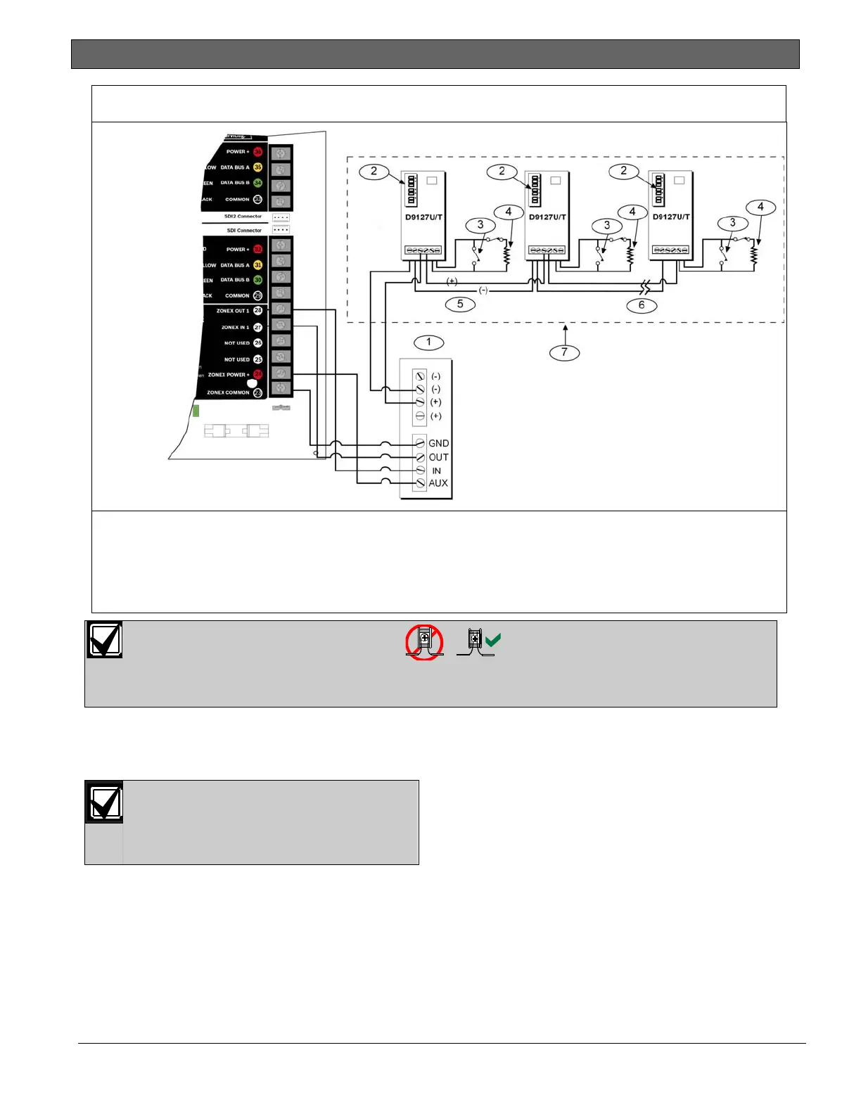
Figure 16: Connecting the D8125 POPEX to the D7412GV4 Control Panel
1 - D8125 POPEX Module
2 - Switch block
3 - D9127 Sensor Loop
4 - 33 k Ω EOL resistor (P/N: P106F [15-03130-
002], package of eight)
5 - Point expansion loop
6 - Up to 119 POPITs
7 - Expansion points
For system supervision, do not use looped wire terminals. Break the wire run to provide
supervision of the connections.
9.3 Installing the D8125 POPEX
Module
For information on the Multiplex Bus
Interface, refer to the D8125MUX
Multiplex Bus Interface Operation and
Installation Guide (P/N: F01U034973).
Save the POPIT Label Sheets: The D8125 is
packaged with two sets of POPIT label sheets.
One set is marked “Bank 1” for use with the
D7412GV4. The other set is marked “Bank 2” for
use with the D9412GV4 and D9112. Use the
sheets later to label the POPITs. Refer to Section
9.3.6 POPIT Module Point Assignments on page 50.
9.3.1 Mounting
To install the D8125 in the enclosure with the
control panel:
1. Align the D8125 POPEX Module with any of
the four mounting locations in the enclosure
(Figure 2 on page 20).
2. Using the screws provided with the module,
secure it in the enclosure.
9.3.2 Wiring the D8125 to the Control Panel
To wire one or two D8125 Modules to the control
panel (Figure 15 on page 47 or Figure 16 on page
48):
Power Down the Control Panel: Disconnect the
positive (red) battery lead at the battery and
unplug the transformer.

 Loading...


