D9412GV4/D7412GV4 v2.03 | Installation and System Reference Guide | 11.0 Arming Devices
.
Bosch Security Systems, Inc. | 7/16 | F01U265457-09 66
Each custom function appears on assigned
keypads with a name you programmed in RPS.
When you assign a custom function as a keypad’s
Shortcuts menu option, the user can use the
[PREV]/ or [NEXT]/ key to scroll through the
list of custom functions on a B915/B920/B921C,
or view the softkeys for each function on the
B930/B942/B942W.
The user must have the appropriate authority
level enabled for the L## C Function 128-131 to
use the custom function. For more information on
creating custom functions, assigning authority
levels to the functions, and assigning custom
functions to a keypad’s Shortcuts menu, refer to
RPS Help or the Control Panels
(D9412GV4/D7412GV4 v2.03) Program Entry
Guide (P/N: F01U265459).
Custom Functions and RADION keyfobs
Using RPS, you can assign two custom functions
to a RADION keyfob, allowing a user to initiate
the functions wirelessly. For more information,
refer to RPS Help or the D9412GV4/D7412GV4
Program Entry Guide (P/N: F01U265459).
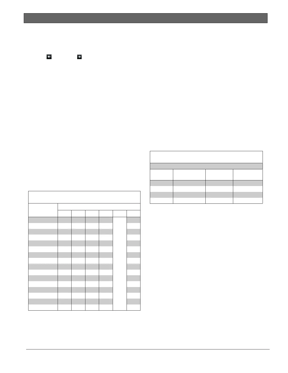
11.2.2 Assigning an Address for the Keypad
Switches on the keypad assign an address (1 to
16). The address determines if the keypad is
supervised, the scope of the keypad, and to what
area the keypad is assigned. Refer to keypad
programming topics found in the compatible
keypad installation guide for a complete
description of addresses.
Table 22 shows the correct switch setting for
each address.
11.2.3 Installation
Refer to the keypad installation manuals for
installation and mounting instructions. Keypads
connect to the control panel in parallel
(Table 22).
Table 22: SDI Keypad Connections
Terminal Function
Keypad
Wire Color
Function
32*
POWER + Red +12.0 VDC
31 DATA BUS A Yellow Data
30 DATA BUS B Green Data
29 COMMON Black Common
* Connect with at least 5 ft (1.5 m) of 22 AWG (0.8 mm) wire
(14 ft [4.3 m] of 18 AWG [1.2 mm] wire).
Switching the Green and Yellow Wires Affects
Other Keypads: Connecting the green wire
incorrectly from the keypad to Terminal 31 and
the yellow wire to Terminal 30 causes other
keypads connected to the control panel to go
blank or to sound random beep tones.
You can connect devices to the data bus
(Terminals 30 and 31) by parallel wire run from
the control panel to each device, wire from
device to device, or a combination of the two
using a maximum of 15000 ft (4572 m) of 22
AWG (0.8 mm) wire for all devices connected to
the SDI Bus combined.
Wire Limits for Individual Devices
Refer to the installation instructions for each
device for wire length specifications.
Table 21: SDI Keypad Address Settings
Address Switch
1 2 3 4 5 6
Address #1 ON ON ON ON
Encoding
Tone ON/OFF
ON
Address #2 OFF ON ON ON ON
Address #3 ON OFF ON ON ON
Address #4 OFF OFF ON ON ON
Address #5 ON ON OFF ON ON
Address #6 OFF ON OFF ON ON
Address #7 ON OFF OFF ON ON
Address #8 OFF OFF OFF ON ON
Address #9 ON ON ON OFF ON
Address #10 OFF ON ON OFF ON
Address #11 ON OFF ON OFF ON
Address #12 OFF OFF ON OFF ON
Address #13 ON ON OFF OFF ON
Address #14 OFF ON OFF OFF ON
Address #15 ON OFF OFF OFF ON
Address #16 OFF OFF OFF OFF ON

 Loading...


