D9412GV4/D7412GV4 v2.03 | Installation and System Reference Guide | 11.0 Arming Devices
.
Bosch Security Systems, Inc. | 7/16 | F01U265457-09 67
Extra Power for More Keypads
The D1255 and D1255B Keypads draw 104 mA
when idle. They draw 206 mA with the keys lit
and the sounder activated. Review Section 6.0
Power Outputs on page 34 to determine the total
power output requirements for the system.
One or more B520 Auxiliary Power Supply
Modules can be added for the number of keypads
used. Figure 26 on page 67 shows the B520
powering keypads.
For UL Certificated accounts, use a UL Listed
auxiliary 12.0 VDC or 24 VDC regulated, power-
limited power supply for Fire Protective Signaling
Units and Commercial or Residential Burglar
Units, such as the B520.
The control panel and the D8132 (or B520 Auxiliary Power Supply Module) must
share COMMON.
Figure 26 on page 65 shows the common form of the D8132 Module connected to
the common on the keypad and the common on the control panel. Any stand-alone
power supply powering any device connected to the control panel must also be
connected to a common terminal on the control panel.
If using the ground fault detection capability on the control panels with an external
power supply, ensure that the external selected power supply isolates its earth
ground connection from the negative side of the auxiliary power output. External
power supplies that do not isolate earth ground can cause ground fault conditions
on the control panel.
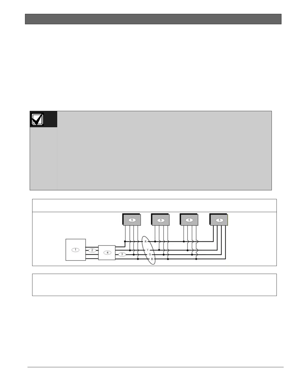
Figure 26: External Power to SDI2 Devices
1 - GV4 control panel
2 - SDI2
3 - SDI2 Out
4 - B520 Auxiliary Power Supply Module
5 - Device to be powered by external source
11.3 D279A Independent Zone Control
Any point can be programmed so that the
D279A Independent Zone Control operates as
independent point control (turning on and off
the point).
Refer to Point Assignments in the Control Panels
(D9412GV4/D7412GV4 v2.03) Program Entry
Guide (P/N: F01U265459) for programming
information. Refer to the D279A Operation and
Installation Instructions (P/N: 46458) for wiring
and operation instructions.

 Loading...


