Safety
Information
Introduction
Product
Information
System
configuration
Mechanical
Installation
Electrical
Installation
Getting
Started
Basic
parameters
Running
the motor
Optimization
SMARTCARD
operation
Onboard
PLC
Advanced
parameters
Technical
Data
Diagnostics
UL Listing
Information
Unidrive SPM User Guide 101
Issue Number: 3 www.controltechniques.com
7 Getting Started
The red stop button is also used to reset the drive.
Both the SM-Keypad and the SM-Keypad Plus can indicate when a SMARTCARD access is taking place or when the second motor map is active
(menu 21). These are indicated on the displays as follows.
7.2 Keypad operation
7.2.1 Control buttons
The keypad consists of:
1. Joypad - used to navigate the parameter structure and change parameter values.
2. Mode button - used to change between the display modes – parameter view, parameter edit, status.
3. Three control buttons - used to control the drive if keypad mode is selected.
4. Help button (SM-Keypad Plus only) - displays text briefly describing the selected parameter.
The Help button toggles between other display modes and parameter help mode. The up and down functions on the joypad scroll the help text to
allow the whole string to be viewed. The right and left functions on the joypad have no function when help text is being viewed.
The display examples in this section show the SM-Keypad 7 segment LED display. The examples are the same for the SM-Keypad Plus except that
the information displayed on the lower row on the SM-Keypad is displayed on the right hand side of the top row on the SM-Keypad Plus.
This chapter introduces the user interfaces, menu structure and security level of the drive.
7.1 Understanding the display
There are two keypads available for the Unidrive SP. The SM-Keypad has an LED display and the SM-Keypad Plus has an LCD display. Both
keypads can be installed on the drive but the SM-Keypad Plus can also be remotely mounted on an enclosure door.
7.1.1 SM-Keypad (LED)
The display consists of two horizontal rows of 7 segment LED displays.
The upper display shows the drive status or the current menu and
parameter number being viewed.
The lower display shows the parameter value or the specific trip type.
7.1.2 SM-Keypad Plus (LCD)
The display consists of three lines of text.
The top line shows the drive status or the current menu and parameter
number being viewed on the left, and the parameter value or the specific
trip type on the right.
The lower two lines show the parameter name or the help text.
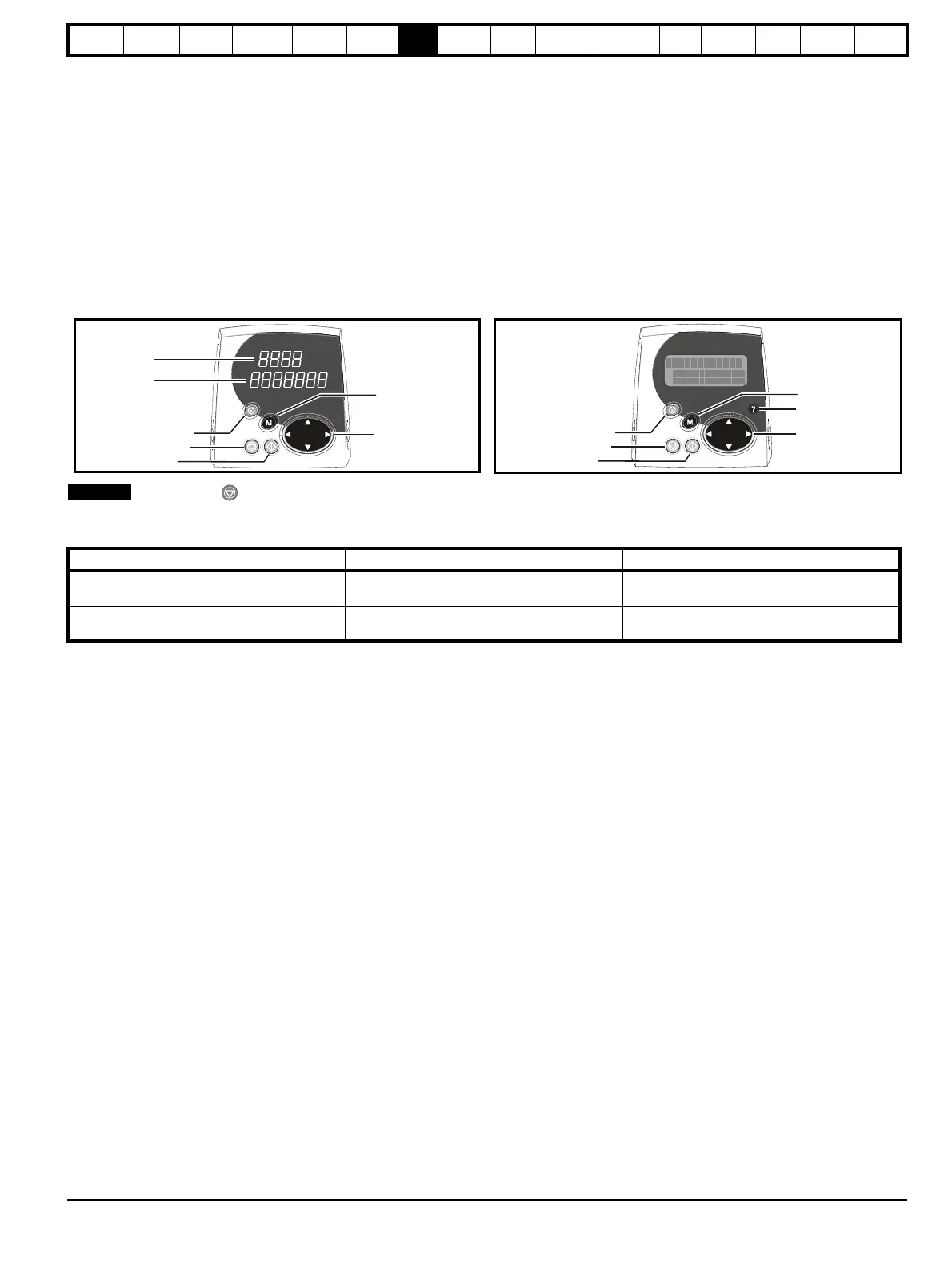
Figure 7-1 SM-Keypad Figure 7-2 SM-Keypad Plus
Upper display
Lower display
Mode (black) button
Joypad
Fwd / Rev (blue) button
Stop/reset (red) button
Start (green) button
Control buttons
Joypad
Fwd / Rev (blue) button
Stop/reset (red) button
Start (green) button
Control buttons
SM-Keypad SM-Keypad Plus
SMARTCARD access taking place
The decimal point after the fourth digit in the
upper display will flash.
The symbol ‘CC’ will appear in the lower left
hand corner of the display
Second motor map active
The decimal point after the third digit in the
upper display will flash.
The symbol ‘Mot2’ will appear in the lower left
hand corner of the display

 Loading...


