Safety
Information
Introduction
Product
Information
System
configuration
Mechanical
Installation
Electrical
Installation
Getting
Started
Basic
parameters
Running
the motor
Optimization
SMARTCARD
operation
Onboard
PLC
Advanced
parameters
Technical
Data
Diagnostics
UL Listing
Information
116 Unidrive SPM User Guide
www.controltechniques.com Issue Number: 3
Figure 8-2 Fixed and variable V/f characteristics
Closed-loop
Pr 0.09 (3.12) operates in the feedback path of the speed-control loop in
the drive. See Figure 13-4 on page 174 for a schematic of the speed
controller. For information on setting up the speed controller gains, refer
to Chapter 10 Optimization on page 136.
8.2.5 Monitoring
Open-loop
Pr 0.10 (5.04) indicates the value of motor speed that is estimated from
the following:
0.12 Post-ramp frequency reference
0.42 Motor - no. of poles
Closed-loop
Pr 0.10 (3.02) indicates the value of motor speed that is obtained from
the speed feedback.
Open-loop & closed loop vector
Pr 0.11 displays the frequency at the drive output.
Servo
Pr 0.11 displays the position of the encoder in mechanical values of 0 to
65,535. There are 65,536 units to one mechanical revolution.
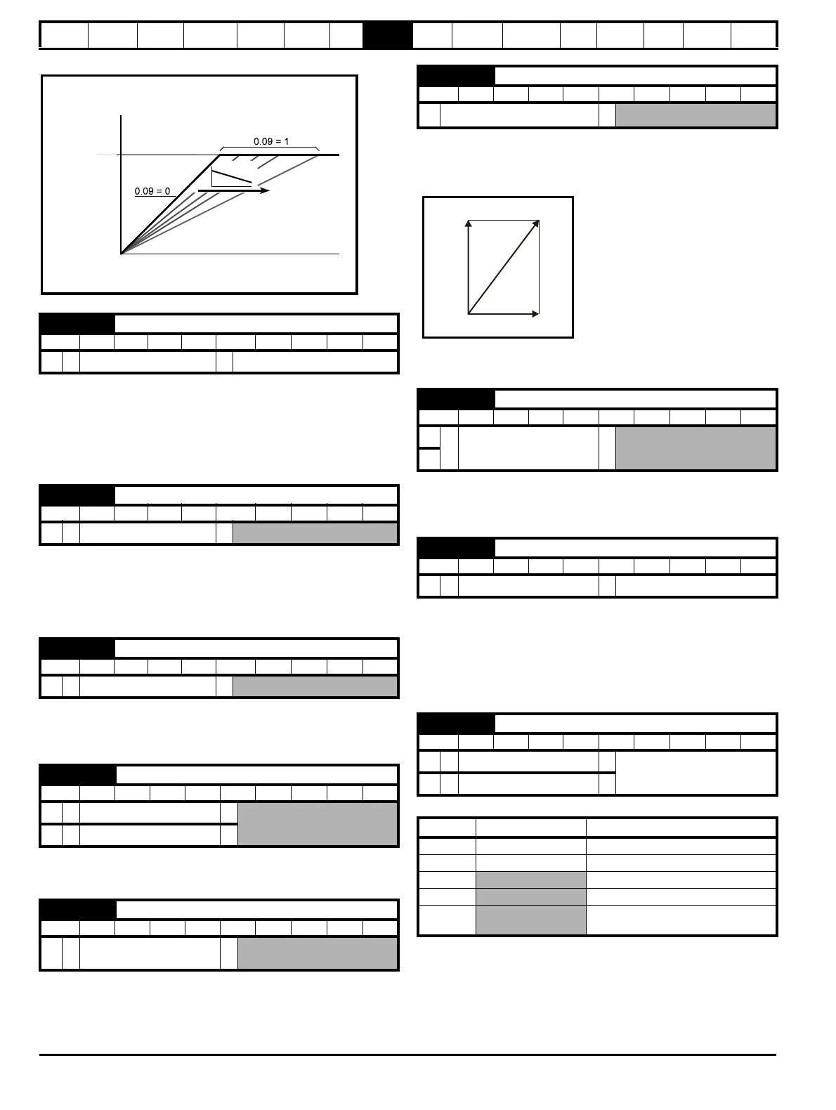
Pr 0.12 displays the rms value of the output current of the drive in each
of the three phases. The phase currents consist of an active component
and a reactive component, which can form a resultant current vector as
shown in the following diagram.
The active current is the torque producing current and the reactive
current is the magnetising or flux-producing current.
Open-loop & closed loop vector
When the motor is being driven below its rated speed, the torque is
proportional to [0.13].
Servo
Pr 0.13 can be used to trim out any offset in the user signal to analog
input 1.
8.2.6 Jog reference, Ramp mode selector, Stop and
torque mode selectors
Pr
0.14
is used to select the required control mode of the drive as follows:
0.09 {3.12} Speed controller differential feedback gain
RW Uni US
CL
Ú
0.00000 to 0.65535(s)
Ö
0.00000
0.10 {5.04} Estimated motor speed
RO Bit FI NC PT
OL
Ú
±180,000 rpm
Ö
0.10 {3.02} Motor speed
RO Bi FI NC PT
VT
Ú
±Speed_max rpm
Ö
0.11 {5.01} Drive output frequency
RO Bi FI NC PT
OL
Ú
±SPEED_FREQ_MAX Hz
Ö
VT
Ú
±1250.0 Hz
Ö
0.11 {3.29} Drive encoder position
RO Uni FI NC PT
SV
Ú
0 to 65,535
1/2
16
ths of a revolution
Ö
Motor
voltage
Frequency
AC supply
voltage
IMOTOR
0.12 {4.01} Total motor current
RO Uni FI NC PT
Ú
0 to Drive_current_max A
Ö
0.13 {4.02} Motor active current
RO Bi FI NC PT
OL
Ú
±Drive_current_max A
Ö
VT
0.13 {7.07} Analog input 1 offset trim
RW Bi US
SV
Ú
±10.000 %
Ö
0.000
0.14 {4.11} Torque mode selector
RW Uni US
OL
Ú
0 to 1
Ö
Speed control (0)
CL
Ú
0 to 4
Ö
Setting Open-Loop Closed-Loop
0 Frequency control Speed control
1 Torque control Torque control
2
Torque control with speed override
3
Coiler/uncoiler mode
4
Speed control with torque feed-
forward
Active
current
Total current
Magnetising current

 Loading...


