Safety
Information
Introduction
Product
Information
System
configuration
Mechanical
Installation
Electrical
Installation
Getting
Started
Basic
parameters
Running
the motor
Optimization
SMARTCARD
operation
Onboard
PLC
Advanced
parameters
Technical
Data
Diagnostics
UL Listing
Information
96 Unidrive SPM User Guide
www.controltechniques.com Issue Number: 3
Refer to section 6.19 SAFE TORQUE OFF (SECURE DISABLE) on page 99
for further information.
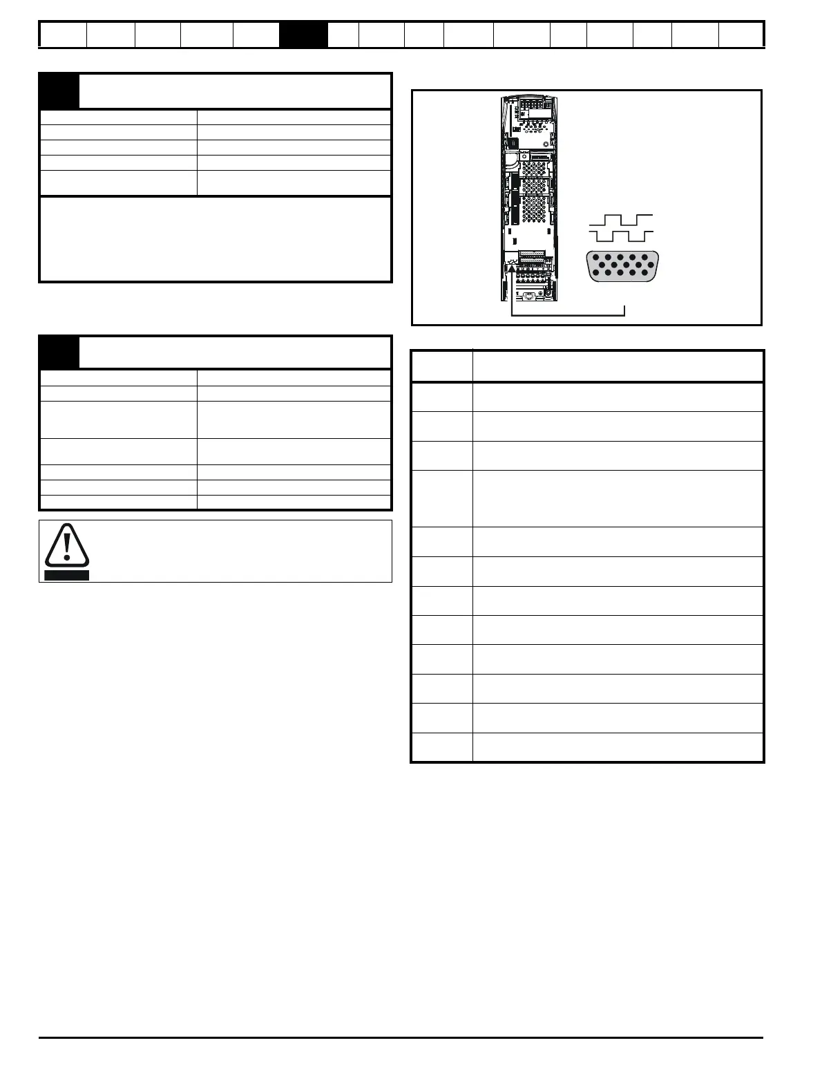
6.18 Encoder connections
Figure 6-44 Location of encoder connector
Table 6-29 Encoder types
* This feedback device provides very low resolution feedback and should
not be used for applications requiring a high level of performance
** The U, V & W commutation signals are required with an incremental
type encoder when used with a servo motor. The UVW commutation
signals are used to define the motor position during the first 120
°
electrical
rotation after the drive is powered-up or the encoder is initialized.
31
Drive enable (SAFE TORQUE OFF (SECURE DISABLE)
function)
Type Positive logic only digital input
Voltage range 0V to +24V
Absolute maximum applied voltage ±30V
Thresholds 15.5V ±2.5V
Response time
Nominal: 8ms
Maximum: 20ms
The drive enable terminal (T31) provides a SAFE TORQUE OFF
(SECURE DISABLE) function. The SAFE TORQUE OFF (SECURE
DISABLE) function meets the requirements of EN954-1 category 3 for
the prevention of unexpected starting of the drive. It may be used in a
safety-related application in preventing the drive from generating
torque in the motor to a high level of integrity.
41
Relay contacts
42
Default function
Drive OK indicator
Contact voltage rating 240Vac, Installation over-voltage category II
Contact maximum current rating
2A AC 240V
4A DC 30V resistive load
0.5A DC 30V inductive load (L/R = 40ms)
Contact minimum recommended
rating
12V 100mA
Contact type Normally open
Default contact condition Closed when power applied and drive OK
Update period 4ms
A fuse or other over-current protection should be installed in
the relay circuit.
Setting of
Pr 3.38
Description
Ab
(0)
Quadrature incremental encoder with or without marker pulse
Fd
(1)
Incremental encoder with frequency pulses and direction,
with or without marker pulse
Fr
(2)
Incremental encoder with forward pulses and reverse
pulses, with or without marker pulse
Ab.SErVO
(3)
Quadrature incremental encoder with UVW commutation
signals, with or without marker pulse
Encoder with UVW commutation signals only (Pr 3.34 set
to zero)*
Fd.SErVO
(4)
Incremental encoder with frequency pulses and direction
with commutation signals**, with or without marker pulse
Fr.SErVO
(5)
Incremental encoder with forward pulses and reverse pulses
with commutation signals**, with or without marker pulse
SC
(6)
SinCos encoder without serial communications
SC.HiPEr
(7)
Absolute SinCos encoder with HiperFace serial
communications protocol (Stegmann)
EndAt
(8)
Absolute EndAt serial communications encoder
(Heidenhain)
SC.EndAt
(9)
Absolute SinCos encoder with EnDat serial
communications protocol (Heidenhain)
SSI
(10)
Absolute SSI only encoder
SC.SSI
(11)
Absolute SinCos encoder with SSI
Drive encoder connector
Female 15-way D-type

 Loading...


