Safety
Information
Introduction
Product
Information
System
configuration
Mechanical
Installation
Electrical
Installation
Getting
Started
Basic
parameters
Running
the motor
Optimization
SMARTCARD
operation
Onboard
PLC
Advanced
parameters
Technical
Data
Diagnostics
UL Listing
Information
240 Unidrive SPM User Guide
www.controltechniques.com Issue Number: 3
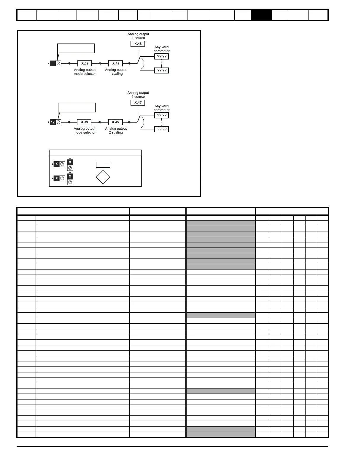
Figure 13-43 SM-I/O 24V Protected analog output logic diagram
SM-I/O 24V Protected parameters
0.XX
0.XX
Key
Read-write (RW)
parameter
Read-only (RO)
parameter
Input
terminals
Output
terminals
The parameters are all shown at their default settings
T12 Analog output 2
T10 Analog output 1
10
Parameter
Range(
Ú) Default(Ö)
Type
x.01 Solutions Module ID 0 to 599 205 RO Uni PT US
x.02
Solutions Module Main Software Version
0.00 to 99.99 RO Uni NC PT
x.03 T5 digital I/O 3 state OFF (0) or On (1) RO Bit NC PT
x.04 T6 digital I/O 4 state OFF (0) or On (1) RO Bit NC PT
x.05 T7 digital input 5 state OFF (0) or On (1) RO Bit NC PT
x.06 T8 digital input 6 state OFF (0) or On (1) RO Bit NC PT
x.07 T9 digital input 7 state OFF (0) or On (1) RO Bit NC PT
x.08 Relay 1 state OFF (0) or On (1) RO Bit NC PT
x.09 T3 digital I/O 1 state OFF (0) or On (1) RO Bit NC PT
x.10 T4 digital I/O 2 state OFF (0) or On (1) RO Bit NC PT
x.11 T3 digital I/O 1 invert OFF (0) or On (1) OFF (0) RW Bit US
x.12 T4 digital I/O 2 invert OFF (0) or On (1) OFF (0) RW Bit US
x.13 T5 digital I/O 3 invert OFF (0) or On (1) OFF (0) RW Bit US
x.14 T6 digital I/O 4 invert OFF (0) or On (1) OFF (0) RW Bit US
x.15
T7 digital input 5 invert
OFF (0) or On (1) OFF (0) RW Bit US
x.16
T8 digital input 6 invert
OFF (0) or On (1) OFF (0) RW Bit US
x.17
T9 digital input 7 invert
OFF (0) or On (1) OFF (0) RW Bit US
x.18 Relay 1 invert OFF (0) or On (1) OFF (0) RW Bit US
x.20 Digital I/O read word 0 to 255 RO Uni NC PT
x.21 T3 digital I/O 1 source/destination Pr 0.00 to Pr 21.51 Pr 0.00 RW Uni DE US
x.22 T4 digital I/O 2 source/destination Pr 0.00 to Pr 21.51 Pr 0.00 RW Uni DE US
x.23 T5 digital I/O 3 source/destination Pr 0.00 to Pr 21.51 Pr 0.00 RW Uni DE US
x.24 T6 digital I/O 4 source/destination Pr 0.00 to Pr 21.51 Pr 0.00 RW Uni DE US
x.25 T7 digital input 5 destination Pr 0.00 to Pr 21.51 Pr 0.00 RW Uni DE US
x.26 T8 digital input 6 destination Pr 0.00 to Pr 21.51 Pr 0.00 RW Uni DE US
x.27 T9 digital input 7 destination Pr 0.00 to Pr 21.51 Pr 0.00 RW Uni DE US
x.28 Relay 1 source Pr 0.00 to Pr 21.51 Pr 0.00 RW Uni US
x.29 T6 digital I/O 4 output select OFF (0) or On (1) On (1) RW Bit US
x.31 T3 digital I/O 1 output select OFF (0) or On (1) OFF (0) RW Bit US
x.32 T4 digital I/O 2 output select OFF (0) or On (1) OFF (0) RW Bit US
x.33 T5 digital I/O 3 output select OFF (0) or On (1) OFF (0) RW Bit US
x.39 Analog output mode
0-20, 20-0, 4-20, 20-4
0-20 RW Uni US
x.40 Relay 2 state 0.0 or 100.0 % RO Bit NC PT
x.42 Relay 2 invert OFF (0) or On (1) OFF (0) RW Bit US
x.43 Relay 2 source Pr 0.00 to Pr 21.51 Pr 0.00 RW Uni US
x.45 Analog output 2 scaling 0.000 to 4.000 1.000 RW Uni US
x.47 Analog output 2 source Pr 0.00 to Pr 21.51 Pr 0.00 RW Uni US
x.48 Analog output 1 source Pr 0.00 to Pr 21.51 Pr 0.00 RW Uni US
x.49 Analog output 1 scaling 0.000 to 4.000 1.000 RW Uni US
x.50 Solutions Module error status 0 to 255 RO Uni NC PT
x.51
Solutions Module software sub-version
0 to 99 RO Uni NC PT

 Loading...


