Safety
Information
Introduction
Product
Information
System
configuration
Mechanical
Installation
Electrical
Installation
Getting
Started
Basic
parameters
Running
the motor
Optimization
SMARTCARD
operation
Onboard
PLC
Advanced
parameters
Technical
Data
Diagnostics
UL Listing
Information
66 Unidrive SPM User Guide
www.controltechniques.com Issue Number: 3
For the dual rectifier, the power connections are repeated. See Figure 2-
4 on page 9 for terminal identification.
A docking kit is available for electronically connecting the SPMD
(inverter) to the SPMC/U (rectifier). See section 5.6.1 Installing the
docking kit on page 39 for further details.
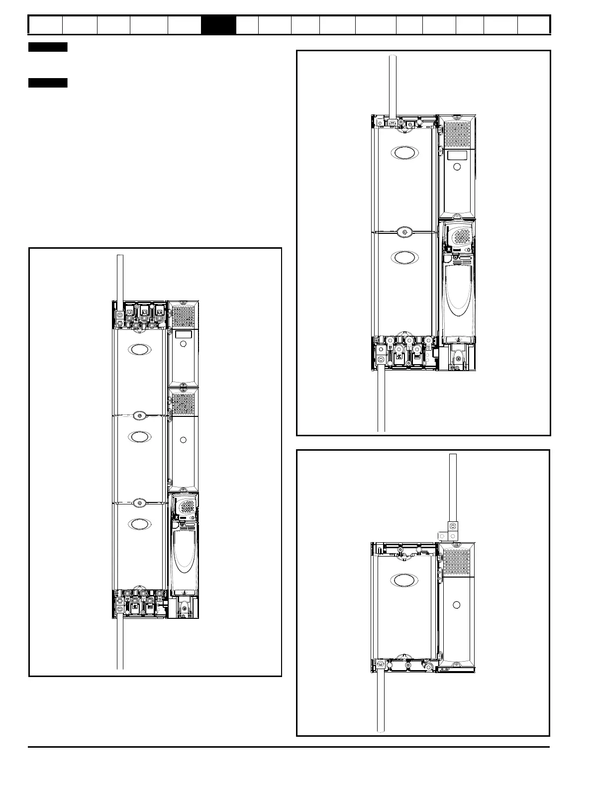
6.1.2 Ground connections
On a Unidrive SPMA, SPMD, SPMC/U the supply and motor ground
connections are made using an M10 bolt at the top (supply) and bottom
(motor) of the drive. See Figure 6-3 on page 66.
The supply ground and motor ground connections to the drive are
connected internally by a copper conductor with a cross-sectional area
given below:
SPMA: 75mm
2
SPMD: 120mm
2
SPMC/U: 128mm
2
Figure 6-3 Unidrive SPMA ground connections
Figure 6-4 Unidrive SPMD ground connections
Figure 6-5 Unidrive SPMC/U ground connections

 Loading...


