Safety
Information
Introduction
Product
Information
System
configuration
Mechanical
Installation
Electrical
Installation
Getting
Started
Basic
parameters
Running
the motor
Optimization
SMARTCARD
operation
Onboard
PLC
Advanced
parameters
Technical
Data
Diagnostics
UL Listing
Information
Unidrive SPM User Guide 89
Issue Number: 3 www.controltechniques.com
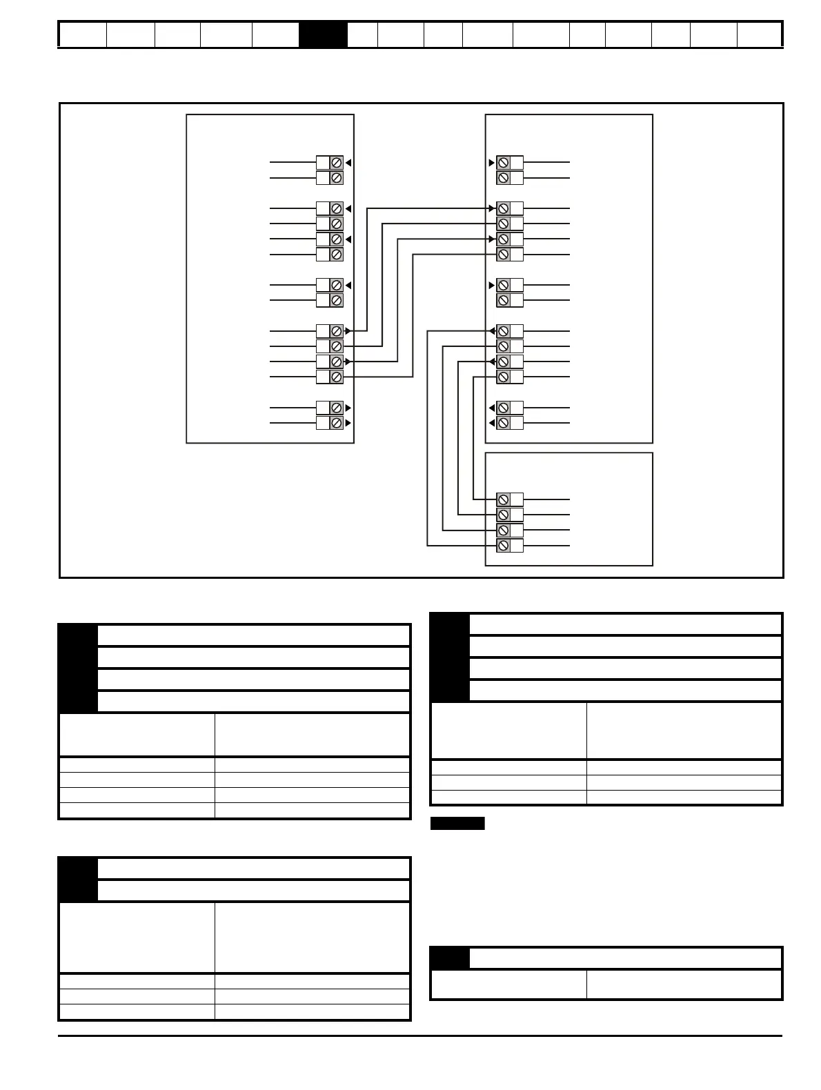
6.14.2 SPMC/U Hardware configuration - Multiple
Rectifier modules
Figure 6-37 Parallel rectifier control terminals and descriptions
6.14.3 Unidrive SPMC/U control connections
Status input connections
Fan control connections
Status output connections
N
When a system contains paralleled Unidrive SPMC/Us, the rectifier’s
status outputs must be daisy chained to the status inputs of the next.
Providing the system is fused correctly, the method used to monitor the
rectifier status must have the ability to disable the system within 500ms.
A PLC can be used to monitor the status output of the rectifier. PLC input
impedance must be no greater than 10kΩ. Status signals are not
latched.
0V common
SPMC/U 2
73
72
Status input 0
0V common
71
Status input 1
0V common
85
84
Rectifier OK
75
74
Fan control
0V common
SPMC/U 1
73
72
Status input 0
0V common
71
Status input 1
0V common
85
84
External 24V
supply
0V common
83
82
Status output 0
0V common
81
80
Status output 1
0V common
70
91
90
Relay contacts
Rectifier OK
70 0V common
71 Status input 1
72 0V common
73 Status input 0
Function
To allow status monitoring for
applications using more than one
rectifier
Logic 0 voltage level <8.4V
Logic 1 voltage level >8.4V
Open circuit voltage level -4.8V source resistance 8.7k
Input resistance
15k
Ω
74 0V common
75 Fan control
Function
The internal fan in the rectifier is
controlled by a temperature control
loop. The fan can be forced to run
at full speed by connecting this
terminal to +24V
Voltage range 0V to 24V supply voltage +2V
Input threshold 10V
Input resistance
6.8k
Ω
80 0V common
81 Status output 1
82 0V common
83 Status output 0
Function
Provides status monitoring from
the rectifier to the connecting drive
/ monitoring equipment to trip the
rectifier unit
Logic 0 voltage level 0V
Logic 1 voltage level 24V supply voltage
Source resistance 1k1
84 0V common
Function
Common connection for all external
devices

 Loading...


