Safety
Information
Introduction
Product
Information
System
configuration
Mechanical
Installation
Electrical
Installation
Getting
Started
Basic
parameters
Running
the motor
Optimization
SMARTCARD
operation
Onboard
PLC
Advanced
parameters
Technical
Data
Diagnostics
UL Listing
Information
Unidrive SPM User Guide 147
Issue Number: 3 www.controltechniques.com
Alternatively the thermal time constant can be calculated from the trip
time with a given current from:
Pr 4.15 = -T
trip
/ ln(1 - (K / Overload)
2
)
The maximum value for the thermal time constant can be increased up
to a maximum value of 3000s to allow an increased overload if the motor
thermal characteristics permit.
For applications using CT Dynamics Unimotors the thermal time
constants can be found in the Unimotor manual.
10.5 Switching frequency
The default switching frequency is 3kHz (6kHz in Servo mode), however
this can be increased up to a maximum of 16kHz by Pr 5.18 (dependent
on drive size). The available switching frequencies are shown below.
Table 10-1 Available switching frequencies
If switching frequency is increased from 3kHz the following apply:
1. Increased heat loss in the drive, which means that derating to the
output current must be applied.
See the derating tables for switching frequency and ambient
temperature in section 14.1.1 Power and current ratings (Derating
for switching frequency and temperature) on page 263.
2. Reduced heating of the motor - due to improved output waveform
quality.
3. Reduced acoustic noise generated by the motor.
4. Increased sample rate on the speed and current controllers. A trade
off must be made between motor heating, drive heating and the
demands of the application with respect to the sample time required.
Table 10-2 Sample rates for various control tasks at each
switching frequency
10.6 High speed operation
10.6.1 Encoder feedback limits
The maximum encoder frequency should be prevented from exceeding
500kHz (or 410kHz for software V01.06.00 and earlier). In closed loop and
servo modes the maximum speed that can be entered in to the speed
reference clamps (Pr
1.06
and Pr
1.07
) can be limited by the drive. This is
defined by the following (subject to an absolute maximum of 40,000rpm):
Where:
ELPR is the equivalent encoder lines per revolution and is the
number of lines that would be produced by a quadrature encoder.
• Quadrature encoder ELPR = number of lines per revolution
• F and D encoder ELPR = number of lines per revolution / 2
• SINCOS encoder ELPR = number of sine waves per revolution
This maximum speed limit is defined by the device selected with the
speed feedback selector (Pr 3.26), and the ELPR set for the position
feedback device. In closed-loop vector mode it is possible to disable this
limit via Pr 3.24, so that the drive can be switched between operation
with and without feedback when the speed becomes too high for the
feedback device. The maximum speed limit is defined as above when
Pr 3.24 = 0 or 1, and is 40,000rpm when Pr 3.24 = 2 or 3.
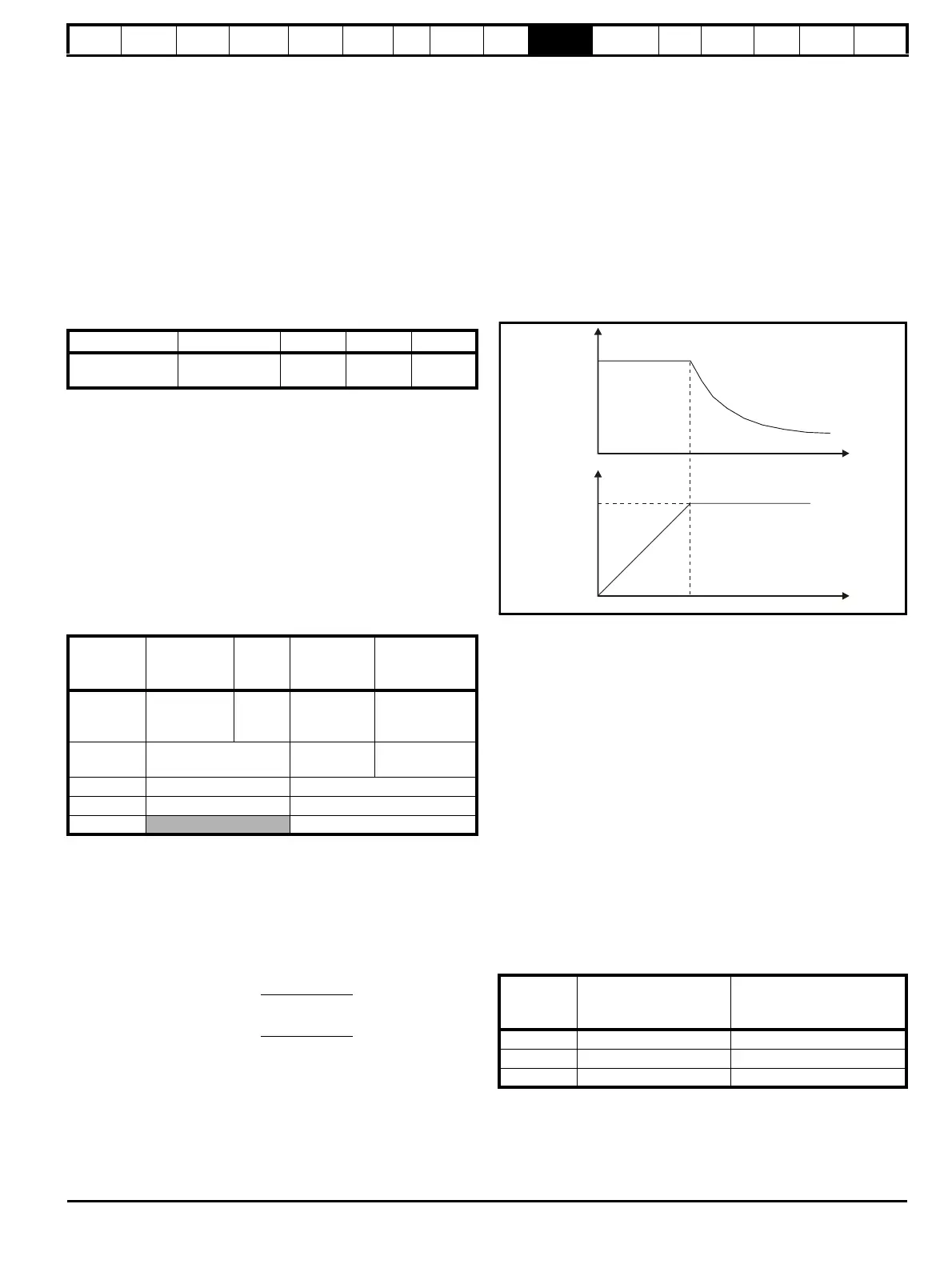
10.6.2 Field weakening (constant power) operation
(Open loop and closed loop vector mode only)
The drive can be used to run an induction machine above synchronous
speed into the constant power region. The speed continues to increase
and the available shaft torque reduces. The characteristics below show
the torque and output voltage characteristics as the speed is increased
above the rated value.
Figure 10-3 Torque and rated voltage against speed
Care must be taken to ensure the torque available above base speed is
sufficient for the application to run satisfactorily.
The saturation breakpoint parameters (Pr 5.29 and Pr 5.30) found during
the autotune in closed loop vector mode ensure the magnetising current
is reduced in the correct proportion for the specific motor. (In open loop
mode the magnetising current is not actively controlled.)
10.6.3 Servo high speed operation
High speed servo mode is enabled by setting Pr 5.22 =1. Care must be
taken when using this mode with servo motors to avoid damaging the
drive. The voltage produced by the servo motor magnets is proportional
to speed. For high speed operation the drive must apply currents to the
motor to counter-act the flux produced by the magnets. It is possible to
operate the motor at very high speeds that would give a very high motor
terminal voltage, but this voltage is prevented by the action of the drive.
If however, the drive is disabled (or tripped) when the motor voltages
would be higher than the rating of the drive without the currents to
counter-act the flux from the magnets, it is possible to damage the drive.
If high speed mode is enabled the motor speed must be limited to the
levels given in the table below unless an additional hardware protection
system is used to limit the voltages applied to the drive output terminals
to a safe level.
Ke is the ratio between r.m.s. line to line voltage produced by the motor
and the speed in V/1000rpm. Care must also be taken not to de-
magnetize the motor. The motor manufacturer should always be
consulted before using this mode.
Drive size Voltage rating 3kHz 4kHz 6kHz
SPMA and
SPMD
All 999
3, 6, 12
kHz
4, 8, 16
kHz
Open loop
Closed loop
vector and
Servo
Level 1
3kHz = 167μs
6kHz = 83μs
12kHz = 83μs
125μs Peak limit
Current
controllers
Level 2 250μs
Current limit
and ramps
Speed controller
and ramps
Level 3 1ms Voltage controller
Level 4 4ms Time critical user interface
Background
Non-time critical user interface
Maximum speed limit (rpm) =
500kHz x 60
ELPR
=
3.0 x 10
7
ELPR
Drive
voltage
rating
Maximum motor speed
(rpm)
Maximum safe line to line
voltage at the motor
terminals (V rms)
200 400 x 1000 / (Ke x √2) 400 / √2
400 800 x 1000 / (Ke x √2) 800 / √2
690 1145 x 1000 / (Ke x √2) 1145 / √2

 Loading...


