Safety
Information
Introduction
Product
Information
System
configuration
Mechanical
Installation
Electrical
Installation
Getting
Started
Basic
parameters
Running
the motor
Optimization
SMARTCARD
operation
Onboard
PLC
Advanced
parameters
Technical
Data
Diagnostics
UL Listing
Information
252 Unidrive SPM User Guide
www.controltechniques.com Issue Number: 3
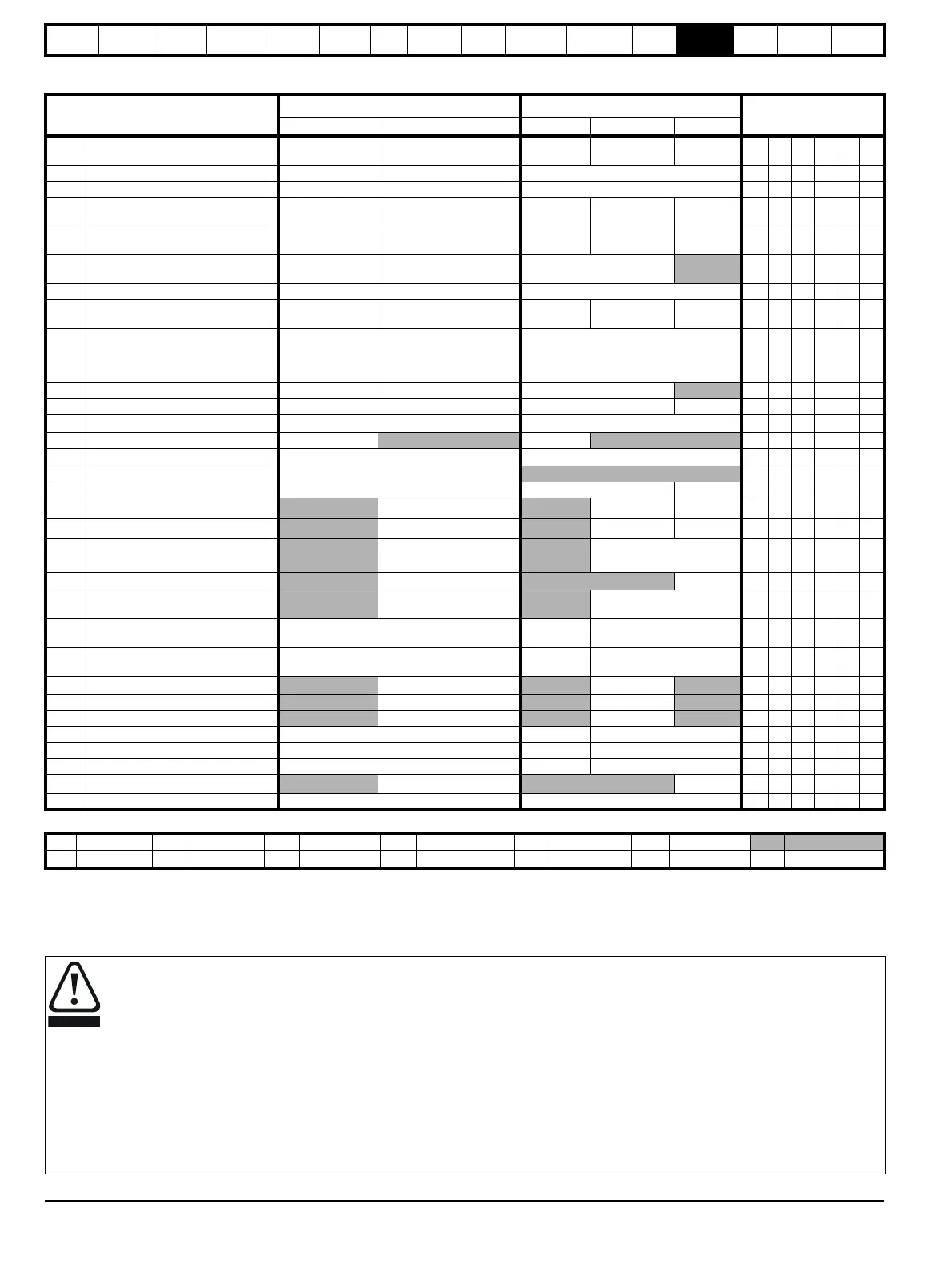
13.19 Menu 21: Second motor parameters
* The menu 0 references are only valid when the second motor map parameters have been made active by setting Pr 11.45 to 1. (The second motor
map only becomes effective when the output stage of the drive is not enabled, i.e. inh, rdY, or trip states.)
When the second motor map parameters are active, the symbol ‘Mot2’ will appear in the lower left hand corner of the LCD display or the decimal point
that is second from the right on the first row of the LED display is lit.
Parameter
Range(
Ú)Default(Ö)
Type
OL CL OL VT SV
21.01
Maximum reference clamp {0.02}* 0 to 3,000.0 Hz SPEED_LIMIT_MAX rpm
EUR> 50.0
USA> 60.0
EUR> 1,500.0
USA> 1,800.0
3,000.0 RW Uni US
21.02 Minimum reference clamp {0.01}* ±3,000.0 Hz ±SPEED_LIMIT_MAX rpm 0.0 RW Bi PT US
21.03 Reference selector {0.05}*
A1.A2 (0), A1.Pr (1), A2.Pr (2), Pr (3), PAd (4), Prc (5)
A1.A2 (0) RW Txt US
21.04 Acceleration rate {0.03}*
0.0 to 3,200.0
s/100Hz
0.000 to 3,200.000
s/1000rpm
5.0 2.000 0.200 RW Uni US
21.05 Deceleration rate {0.04}*
0.0 to 3200.0
s/100Hz
0.000 to 3,200.000
s/1000rpm
10.0 2.000 0.200 RW Uni US
21.06 Rated frequency {0.47}* 0 to 3000.0 Hz VT> 0 to 1250.0Hz
EUR> 50
USA> 60
RW Uni US
21.07 Rated current {0.46}* 0 to RATED_CURRENT_MAX A Drive rated current (Pr 11.32) RW Uni RA US
21.08 Rated load rpm {0.45}* 0 to 180,000 rpm 0.00 to 40,000.00 rpm
EUR> 1,500
USA> 1,800
EUR> 1,450.00
USA> 1,770.00
3,000.00 RW Uni US
21.09 Rated voltage {0.44}* 0 to AC_VOLTAGE_SET_MAX V
200V rating drive: 230V
400V rating drive: EUR> 400V, USA> 460V
575V rating drive: 575V
690V rating drive: 690V
RW Uni RA US
21.10 Rated power factor {0.43}* 0.000 to 1.000 VT> 0.000 to 1.000 0.85 RW Uni RA US
21.11 Number of motor poles {0.42}* Auto to 120 pole (0 to 60) Auto (0) 6 POLE (3) RW Txt US
21.12 Stator resistance
0.000 to 65.000
x 10 mΩ
0.0 RW Uni RA US
21.13 Voltage offset 0.0 to 25.0 V 0.0 RW Uni RA US
21.14
Transient inductance (σL
s)
0.000 to 500.000mH 0.000 RW Uni RA US
21.15 Motor 2 active OFF (0) or On (1) RO Bit NC PT
21.16 Thermal time constant {0.45}* 0.0 to 3000.0 89.0 20.0 RW Uni US
21.17 Speed controller Kp gain {0.07}*
0.000 to 6.5535 rad s
-1
0.0300 0.0100 RW Uni US
21.18 Speed controller Ki gain {0.08}*
0.00 to 655.35 s/rad s
-1
0.10 1.00 RW Uni US
21.19 Speed controller Kd gain {0.09}*
0.00000 to 0.65535
s
-1
/rad s
-1
0.00000 RW Uni US
21.20 Encoder phase angle {0.43}*
0.0 to 359.9 ° electrical
0.0 RW Uni US
21.21 Speed feedback selector
drv (0), SLot1 (1),
SLot2 (2), SLot3 (3)
drv (0) RW Txt US
21.22 Current controller Kp gain {0.38}* 0 to 30,000 20
200V: 75, 400V: 150,
575V: 180, 690V: 215
RW Uni US
21.23 Current controller Ki gain {0.39}* 0 to 30,000 40
200V: 1,000, 400V: 2,000,
575V: 2,400, 690V: 3,000
RW Uni US
21.24
Stator inductance (L
s
)
VT> 0.00 to 5,000.00 mH 0.00 RW Uni RA US
21.25 Motor saturation breakpoint 1 VT> 0 to 100% of rated flux 50 RW Uni US
21.26 Motor saturation breakpoint 2 VT> 0 to 100% of rated flux 75 RW Uni US
21.27 Motoring current limit 0 to MOTOR2_CURRENT_LIMIT_MAX % 165.0 175.0 RW Uni RA US
21.28 Regen current limit 0 to MOTOR2_CURRENT_LIMIT_MAX % 165.0 175.0 RW Uni RA US
21.29 Symmetrical current limit {0.06}* 0 to MOTOR2_CURRENT_LIMIT_MAX % 165.0 175.0 RW Uni RA US
21.30
Motor volts per 1,000 rpm, K
e
SV> 0 to 10,000 V 98 RW Uni US
21.31 Motor pole pitch 0.00 to 655.35 mm 0.00 RW Uni US
RW Read / Write RO Read only Uni Unipolar Bi Bi-polar Bit Bit parameter Txt Text string
FI Filtered DE Destination NC Not copied RA Rating dependent PT Protected US User save PS Power down save
Encoder phase angle (servo mode only)
With drive software version V01.08.00 onwards, the encoder phase angles in Pr
3.25
and Pr
21.20
are copied to the SMARTCARD when using
any of the SMARTCARD transfer methods.
With drive software version V01.05.00 to V01.07.01, the encoder phase angles in Pr
3.25
and Pr
21.20
are only copied to the SMARTCARD
when using either Pr
0.30
set to Prog (2) or Pr
xx.00
set to 3yyy.
This is useful when the SMARTCARD is used to back-up the parameter set of a drive but caution should be used if the SMARTCARD is used to
transfer parameter sets between drives.
Unless the encoder phase angle of the servo motor connected to the destination drive is known to be the same as the servo motor connected
to the source drive, an autotune should be performed or the encoder phase angle should be entered manually into Pr
3.25
(or Pr
21.20
). If the
encoder phase angle is incorrect the drive may lose control of the motor resulting in an O.SPd or Enc10 trip when the drive is enabled.
With drive software version V01.04.00 and earlier, or when using software version V01.05.00 to V01.07.01 and Pr
xx.00
set to 4yyy is used,
then the encoder phase angles in Pr
3.25
and Pr
21.20
are not copied to the SMARTCARD. Therefore, Pr
3.25
and Pr
21.20
in the destination
would not be changed during a transfer of this data block from the SMARTCARD.

 Loading...


