Safety
Information
Introduction
Product
Information
System
configuration
Mechanical
Installation
Electrical
Installation
Getting
Started
Basic
parameters
Running
the motor
Optimization
SMARTCARD
operation
Onboard
PLC
Advanced
parameters
Tec hnic al
Data
Diagnostics
UL Listing
Information
16 Unidrive SPM User Guide
www.controltechniques.com Issue Number: 3
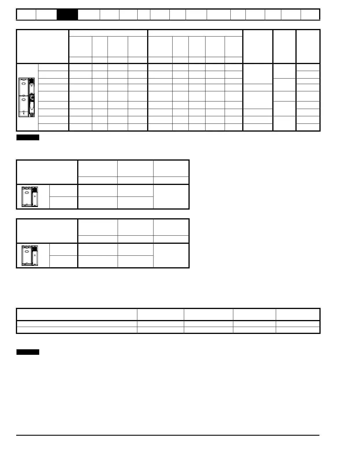
Table 3-10 Paralleled SPMD 690V motor drive ratings (500V to 690V ±10%) based on AC supply voltage
Table 3-11 Unidrive SPMC/U 400V ratings
Table 3-12 Unidrive SPMC/U 690V ratings
3.1.1 Typical short term overload limits
The maximum percentage overload limit changes depending on the selected motor. Variations in motor rated current, motor power factor and motor
leakage inductance all result in changes in the maximum possible overload. The exact value for a specific motor can be calculated using the
equations detailed in Menu 4 in the Unidrive SP Advanced User Guide.
Typical values are shown in the tables below for closed loop vector (VT) and open loop (OL) modes.
Table 3-13 Typical overload limits for all Unidrive SPM modules
Generally the drive rated current is higher than the matching motor rated current allowing a higher level of overload than the default setting.
The time allowed in the overload region is proportionally reduced at very low output frequency on some drive ratings.
The maximum overload level which can be attained is independent of the speed.
Paralleled SPMD modules
Normal Duty Heavy Duty
Required
rectifier
Required
input line
reactor
Required
output
sharing
choke
Maximum
continuous
output
current
Peak
current
Nominal
motor
power at
690V
Nominal
motor
power at
575V
Maximum
continuous
output
current
Open
loop
peak
current
Closed
loop
peak
current
Nominal
motor
power
at 690V
Nominal
motor
power at
575V
A AkW hp A AAkWhp
2 x SPMD16X1 237 261 250 250 190 244 284 200 200
1 x SPMC2601
1 x INL611
1 x OTL611
2 x SPMD16X2 273 300 280 300 237 305 356 250 250 1 x OTL612
2 x SPMD16X3 319 351 315 350 273 351 410 250 300
1 x INL612
1 x OTL613
2 x SPMD16X4 364 401 315 350 319 410 478 280 350 2 x SPMC1601 1 x OTL614
3 x SPMD16X2 410 451 450 450 356 457 534 355 400
1 x SPMC2601
+
1 x SPMC1601
1 x INL611 +
1 x INL601
3 x OTL602
3 x SPMD16X3 478 526 500 500 410 527 615 450 450
1 x INL612 +
1 x INL602
3 x OTL603
3 x SPMD16X4 547 601 545 600 478 615 718 450 500 3 x SPMC1601 3 x OTL604
4 x SPMD16X3 638 702 630 700 547 703 820 545 600 2 x SPMC2601
2 x INL612
4 x OTL603
4 x SPMD16X4 729 802 710 800 638 820 957 630 700 4 x SPMC1601 4 x OTL604
When connecting drives in parallel they must be derated. Table 3-2, Table 3-4, Table 3-6, Table 3-8 and Table 3-10 have already the
required de-rating.
Model
Maximum
AC input current
Maximum DC
output current
External 24V
current
consumption
AAA
SPMC/U1402
344 379
3.0
SPMC/U2402
2 x 312 2 x 345
Model
Maximum AC input
current
Maximum DC
output current
External 24V
current
consumption
AAA
SPMC/U1601 195
209
3.0
SPMC/U2601 2 x 173
2 x 185
Operating mode
Closed loop/RFC/
Servo/Regen from cold
Closed loop/RFC/Servo/
Regen from 100%
Open loop from cold Open loop from 100%
Normal Duty overload with motor rated current = drive rated current 110% for 165s 110% for 9s 110% for 165s 110% for 9s
Heavy Duty overload with motor rated current = drive rated current 150% for 60s 150% for 8s 129% for 97s 129% for 15s

 Loading...


