Safety
Information
Introduction
Product
Information
System
configuration
Mechanical
Installation
Electrical
Installation
Getting
Started
Basic
parameters
Running
the motor
Optimization
SMARTCARD
operation
Onboard
PLC
Advanced
parameters
Technical
Data
Diagnostics
UL Listing
Information
Unidrive SPM User Guide 275
Issue Number: 3 www.controltechniques.com
15 Diagnostics
The display on the drive gives various information about the status of the
drive. These fall into three categories:
• Trip indications
• Alarm indications
• Status indications
15.1 Trip indications
If the drive trips, the output of the drive is disabled so that the drive stops
controlling the motor. The upper display indicates that a trip has
occurred and the lower display shows the trip. If this is a multi-module
drive and a power module has indicated a trip, then the lower display will
alternate between the trip string and the module number.
Trips are listed alphabetically in Table 15-1 based on the trip indication
shown on the drive display. Refer to Figure 15-1.
If a display is not used, the drive LED Status indicator will flash if the
drive has tripped. Refer to Figure 15-2.
The trip indication can be read in Pr 10.20 providing a trip number. Trip
numbers are listed in numerical order in Table 15-2 so the trip indication
can be cross referenced and then diagnosed using Table 15-1.
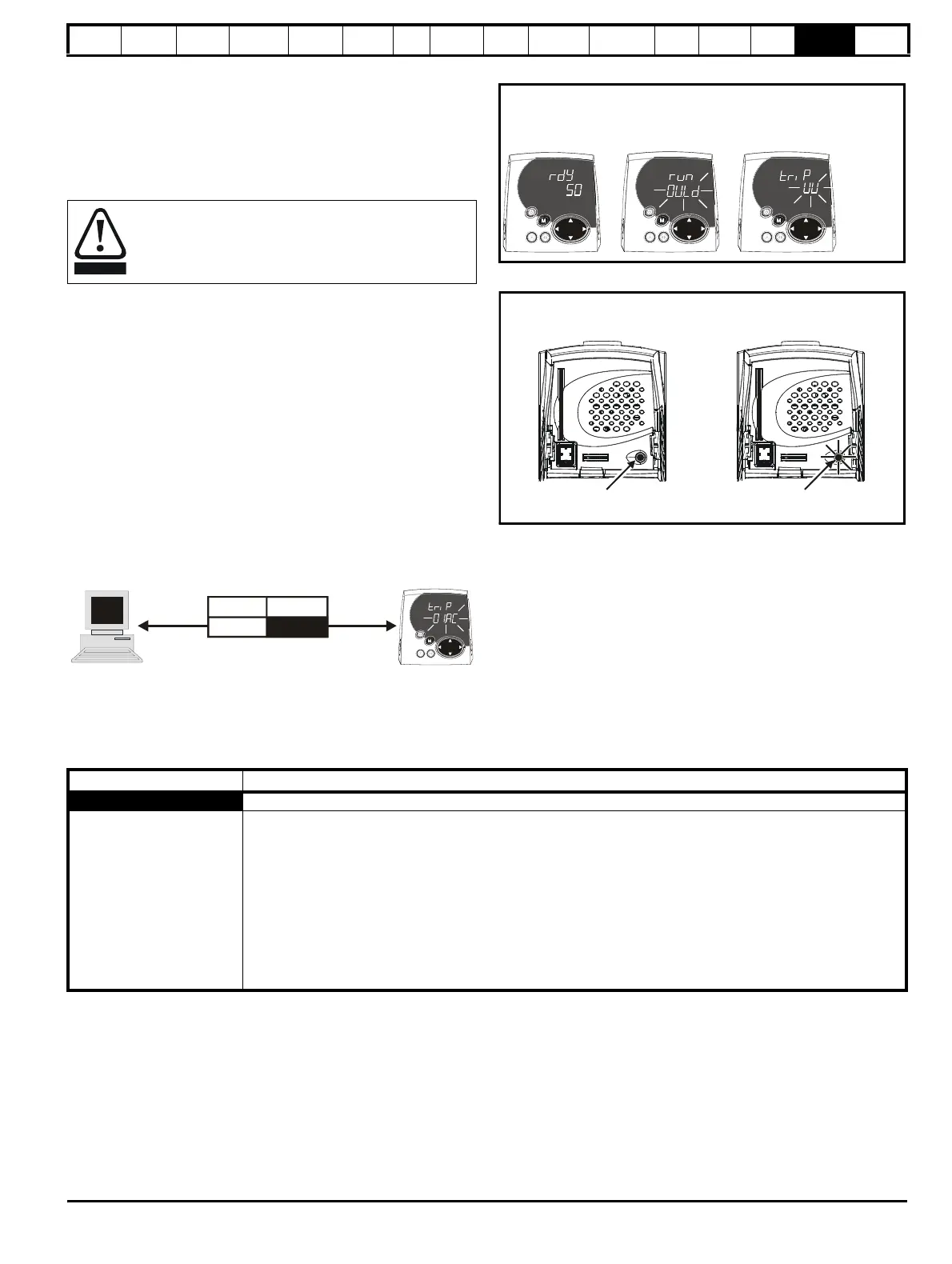
Example
1. Trip code 3 is read from Pr 10.20 via serial communications.
2. Checking Table 15-2 shows Trip 3 is an OI.AC trip.
3. Look up OI.AC in Table 15-1.
4. Perform checks detailed under Diagnosis.
Figure 15-1 Keypad status modes
Figure 15-2 Location of the status LED
Users must not attempt to repair a drive if it is faulty, nor
carry out fault diagnosis other than through the use of the
diagnostic features described in this chapter.
If a drive is faulty, it must be returned to an authorized
Control Techniques distributor for repair.
Keypad
display
Comms
code
No. Trip
3 OI.AC
= undervolts)
Drive status
= tripped
Trip StatusAlarm Status
Healthy Status
Status Mode
Trip Diagnosis
OI.AC Instantaneous output over current detected: peak output current greater than 225%
3
Acceleration / deceleration rate is too short.
If seen during autotune reduce voltage boost Pr 5.15
Check for short circuit on output cabling
Check integrity of motor insulation
Check feedback device wiring
Check feedback device mechanical coupling
Check feedback signals are free from noise
Is motor cable length within limits for that frame size?
Reduce the values in speed loop gain parameters – Pr 3.10, Pr 3.11 and Pr 3.12 (and servo modes only)
Has offset measurement test been completed? (servo mode only)
Reduce the values in current loop gain parameters - Pr 4.13 and Pr 4.14 (closed loop vector and servo modes only)

 Loading...


