Safety
Information
Introduction
Product
Information
System
configuration
Mechanical
Installation
Electrical
Installation
Getting
Started
Basic
parameters
Running
the motor
Optimization
SMARTCARD
operation
Onboard
PLC
Advanced
parameters
Technical
Data
Diagnostics
UL Listing
Information
Unidrive SPM User Guide 67
Issue Number: 3 www.controltechniques.com
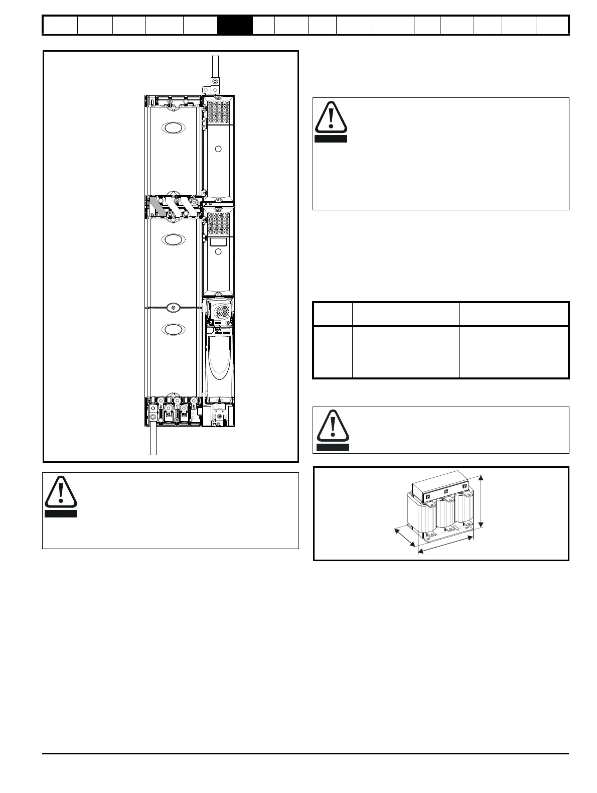
Figure 6-6 Unidrive SPMD and SPMC/U (rectifier) ground connections
6.2 AC supply requirements
Voltage:
SPMX X2XX 200V to 240V ±10%
SPMX X4XX 380V to 480V ±10%
SPMX X6XX 500V to 690V ±10%
Number of phases: 3
Maximum supply imbalance: 2% negative phase sequence (equivalent
to 3% voltage imbalance between phases).
Frequency range: 48 to 62 Hz
The maximum supply symmetrical fault current must be limited to 100kA
(also required for UL compliance).
6.2.1 Supply types
Drives rated for supply voltage up to 575V are suitable for use with any
supply type, i.e. TN-S, TN-C-S, TT, IT, with grounding at any potential,
i.e. neutral, centre or corner ("grounded-delta").
Grounded delta supplies >575V are not permitted.
Drives are suitable for use on supplies of installation category III and
lower, according to IEC60664-1. This means they may be connected
permanently to the supply at its origin in a building, but for outdoor
installation additional over-voltage suppression (transient voltage surge
suppression) must be provided to reduce category IV to category III.
A ground fault in the supply has no effect in any case. If the motor must
continue to run with a ground fault in its own circuit then an input
isolating transformer must be provided and if an EMC filter is required it
must be located in the primary circuit.
Unusual hazards can occur on ungrounded supplies with more than one source,
for example on ships. Contact the supplier of the drive for more information.
Table 6-1 Behaviour of the drive in the event of a ground (earth)
fault with an IT supply
6.2.2 Input line reactor specifications
Figure 6-7 Input line reactor/output sharing choke dimensions
The ground loop impedance must conform to the
requirements of local safety regulations.
The drive must be grounded by a connection capable of
carrying the prospective fault current until the protective
device (fuse, etc.) disconnects the AC supply.
The ground connections must be inspected and tested at
appropriate intervals.
Ground
link
Supply
ground
Motor
ground
Operation with IT (ungrounded) supplies:
Special attention is required when using internal or external
EMC filters with ungrounded supplies, because in the event
of a ground (earth) fault in the motor circuit the drive may not
trip and the filter could be over-stressed. In this case, either
the filter must not be used (removed) or additional
independent motor ground fault protection must be provided.
Refer to Table 6-1.
For instructions on removal, refer to Figure 6-19 on page 80.
For details of ground fault protection contact the supplier of
the drive.
Drive
size
Internal filter only
External filter (with
internal)
SPMA
SPMD
May not trip – precautions
required:
• Remove the EMC filter
• Use ground leakage
relay
May not trip – precautions
required:
• Do not use EMC filter
• Use ground leakage
relay
A separate input line reactor of at least the value shown in
Table 6-2 and Table 6-3 must be used with the rectifiers.
Failure to provide sufficient reactance could damage or
reduce the service life of the rectifier or inverter.

 Loading...


