Safety
Information
Introduction
Product
Information
System
configuration
Mechanical
Installation
Electrical
Installation
Getting
Started
Basic
parameters
Running
the motor
Optimization
SMARTCARD
operation
Onboard
PLC
Advanced
parameters
Technical
Data
Diagnostics
UL Listing
Information
292 Unidrive SPM User Guide
www.controltechniques.com Issue Number: 3
15.2 Alarm indications
In any mode an alarm flashes alternately with the data displayed on the
2nd row when one of the following conditions occur. If action is not taken
to eliminate any alarm except "Autotune", "Lt" and "PLC" the drive may
eventually trip. Alarms flash once every 640ms except "PLC" which
flashes once every 10s. Alarms are not displayed when a parameter is
being edited.
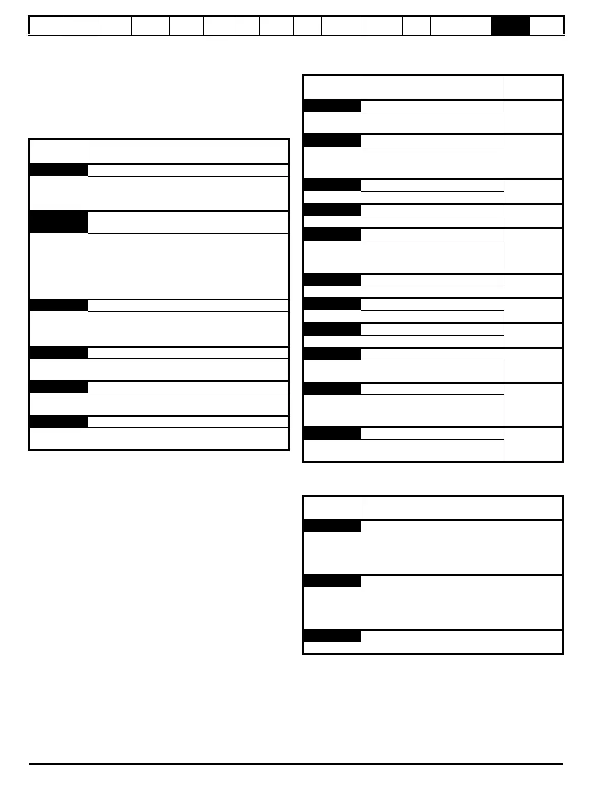
Table 15-4 Alarm indications
15.3 Status indications
Table 15-5 Status indications
Table 15-6 Solutions Module and SMARTCARD status indications
at power-up
Lower
display
Description
br.rS Braking resistor overload
Braking resistor I
2
t accumulator (Pr 10.39) in the drive has reached
75.0% of the value at which the drive will trip and the braking IGBT is
active.
Hot
Heatsink or control board or inverter IGBT over
temperature alarms are active
• The drive heatsink temperature has reached a threshold and the
drive will trip O.ht2 if the temperature continues to rise (see the
O.ht2 trip).
Or
• The ambient temperature around the control PCB is approaching
the over temperature threshold (see the O.CtL trip).
OVLd Motor overload
The motor I
2
t accumulator (Pr 4.19) in the drive has reached 75% of
the value at which the drive will be tripped and the load on the drive is
>100%
Auto tune Autotune in progress
The autotune procedure has been initialised. 'Auto' and 'tunE' will flash
alternatively on the display.
Lt Limit switch is active
Indicates that a limit switch is active and that it is causing the motor to
be stopped (i.e. forward limit switch with forward reference etc.)
PLC Onboard PLC program is running
An Onboard PLC program is installed and running. The lower display
will flash 'PLC' once every 10s.
Upper
display
Description
Drive output
stage
ACt Regeneration mode active
Enabled
The regen unit is enabled and synchronised to the
supply.
ACUU AC Supply loss
Enabled
The drive has detected that the AC supply has been
lost and is attempting to maintain the DC bus voltage
by decelerating the motor.
dc DC applied to the motor
Enabled
The drive is applying DC injection braking.
dEC Decelerating
Enabled
The drive is decelerating the motor.
inh
Inhibit
Disabled
The drive is inhibited and cannot be run.
The drive enable signal is not applied to terminal 31 or
Pr 6.15 is set to 0.
POS Positioning
Enabled
The drive is positioning/orientating the motor shaft.
rdY Ready
Disabled
The drive is ready to be run.
run
Running
Enabled
The drive is running.
SCAn Scanning
Enabled
Regen> The drive is enabled and is synchronising to
the line.
StoP Stop or holding zero speed
Enabled
The drive is holding zero speed.
Regen> The drive is enabled but the AC voltage is too
low, or the DC bus voltage is still rising or falling.
triP Trip condition
Disabled
The drive has tripped and is no longer controlling the
motor. The trip code appears on the lower display.
Lower
display
Description
boot
A parameter set is being transferred from the SMARTCARD to the
drive during power-up. For further information, please refer to section
11.2.4 Booting up from the SMARTCARD on every power up (Pr 11.42
= boot (4)) on page 151.
cArd
The drive is writing a parameter set to the SMARTCARD during power-
up.
For further information, please refer to section 11.2.3 Auto saving
parameter changes (Pr 11.42 = Auto (3)) on page 151.
loAding
The drive is writing information to a Solutions Module.

 Loading...


