Safety
Information
Introduction
Product
Information
System
configuration
Mechanical
Installation
Electrical
Installation
Getting
Started
Basic
parameters
Running
the motor
Optimization
SMARTCARD
operation
Onboard
PLC
Advanced
parameters
Technical
Data
Diagnostics
UL Listing
Information
68 Unidrive SPM User Guide
www.controltechniques.com Issue Number: 3
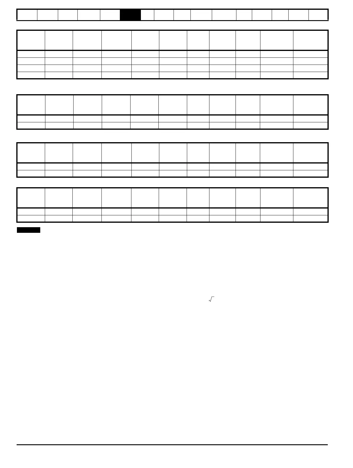
Table 6-2 400V input line reactor ratings
*May represent a more economic solution where operating temperature and cooling requirements are observed.
Table 6-3 400V dual input line reactor ratings
Table 6-4 690V input line reactor ratings
Table 6-5 690V dual input line reactor ratings
N
The INLX1X parallel line reactors have been designed to work in
conjunction with the Unidrive SPMC/U, allowing one reactor to be used
with the dual rectifier model or two separate rectifier units.
6.2.3 Supplies requiring additional line reactance
Additional line reactance reduces the risk of damage to the drive resulting
from poor phase balance or severe disturbances on the supply network. It
also reduces harmonic current emission. It can be implemented by
adding external reactors with SPMA modules, and by adding additional
series reactors or increased reactance values with rectifier modules.
Where additional line reactance is to be used, added reactance of
approximately 2% is recommended. Higher values may be used if
necessary, but may result in a loss of drive output (reduced torque at
high speed) because of the voltage drop.
For all drive ratings, 2% additional reactance permits drives to be used
with a supply unbalance of up to 3.5% negative phase sequence
(equivalent to 5% voltage imbalance between phases).
Severe disturbances may be caused by the following factors, for example:
• Power factor correction equipment connected close to the drive.
• Large DC drives having no or inadequate line reactors connected to
the supply.
• Direct-on-line started motor(s) connected to the supply such that
when any of these motors are started, the voltage dip exceeds 20%.
Such disturbances may cause excessive peak currents to flow in the
input power circuit of the drive. This may cause nuisance tripping, or in
extreme cases, failure of the drive.
Drives of low power rating may also be susceptible to disturbance when
connected to supplies with a high rated capacity.
When required, each drive must have its own reactor(s). Three individual
reactors or a single three-phase reactor should be used.
Reactor current ratings
The current rating of the line reactors should be as follows:
Continuous current rating:
Not less than the continuous input current rating of the drive
Repetitive peak current rating:
Not less than twice the continuous input current rating of the drive
6.2.4 Additional input inductance calculation
To calculate the additional inductance required (at Y%), use the following
equation:
Where:
I = drive rated input current (A)
L = inductance (H)
f = supply frequency (Hz)
V = voltage between lines
Model
Current
A
Inductance
μH
Overall
width (W)
mm
Overall
depth (D)
mm
Overall
height (H)
mm
Weight
kg
Max
ambient
temp (°C)
Min
airflow
(m/s)
Quantity
required
Part No.
INL 401 245 63 240 190 225 32 50 1 1 4401-0181
INL 402 339 44 276 200 225 36 50 1 1 4401-0182
INL 401W* 245 63 255 235 200 27 40 3 1 4401-0208
INL 402W* 339 44 255 235 200 27 40 3 1 4401-0209
Model
Current
A
Inductance
μH
Overall
width (W)
mm
Overall
depth (D)
mm
Overall
height (H)
mm
Weight
kg
Max
ambient
temp (°C)
Min
airflow
(m/s)
Quantity
required
Part No.
INL411 2 x 245 2 x 31.5 320 220 360 55 50 1 1 4401-0206
INL412 2 x 339 2 x 22 320 220 360 55 50 1 1 4401-0207
Model
Current
A
Inductance
μH
Overall
width (W)
mm
Overall
depth (D)
mm
Overall
height (H)
mm
Weight
kg
Max
ambient
temp (°C)
Min
airflow
(m/s)
Quantity
required
Part No.
INL 601 145 178 240 190 225 33 50 1 1 4401-0183
INL 602 192 133 276 200 225 36 50 1 1 4401-0184
Model
Current
A
Inductance
μH
Overall
width (W)
mm
Overall
depth (D)
mm
Overall
height (H)
mm
Weight
kg
Max
ambient
temp (°C)
Min
airflow
(m/s)
Quantity
required
Part No.
INL 611 2 x 145 2 x 89 320 220 360 40 50 1 1 4401-0190
INL 612 2 x 192 2 x 66.5 320 220 360 55 50 1 1 4401-0191
L
Y
100
----------
V
3
-------
×
1
2πfI
------------
×=

 Loading...


