Safety
Information
Introduction
Product
Information
System
configuration
Mechanical
Installation
Electrical
Installation
Getting
Started
Basic
parameters
Running
the motor
Optimization
SMARTCARD
operation
Onboard
PLC
Advanced
parameters
Technical
Data
Diagnostics
UL Listing
Information
158 Unidrive SPM User Guide
www.controltechniques.com Issue Number: 3
13 Advanced parameters
This is a quick reference to all parameters in the drive showing units,
ranges limits etc, with block diagrams to illustrate their function. Full
descriptions of the parameters can be found in the Advanced User
Guide on the supplied CD ROM.
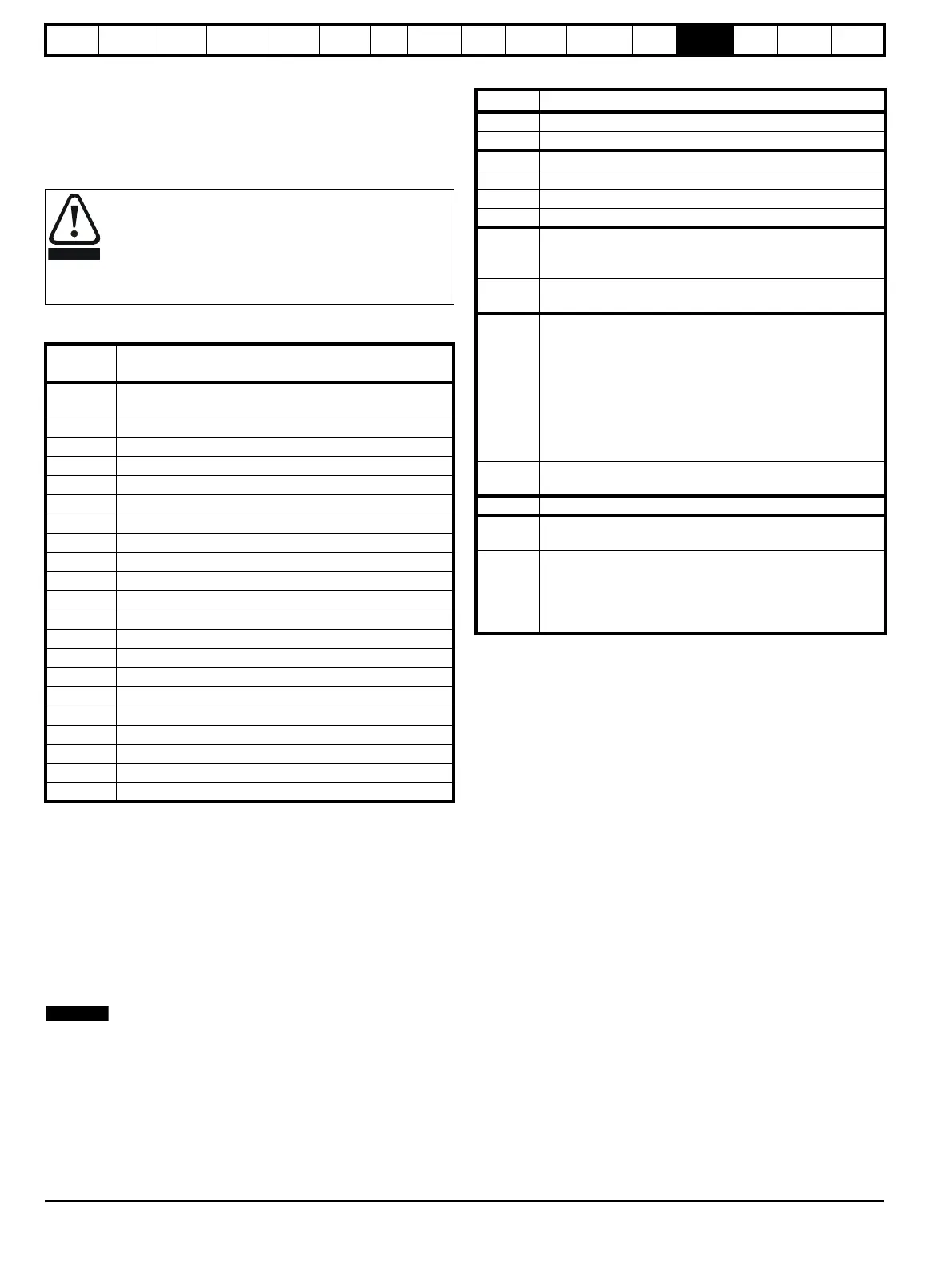
Table 13-1 Menu descriptions
Operation mode abbreviations:
OL> Open loop
CL> Closed loop (which incorporates closed loop vector and
servo mode)
VT> Closed loop vector mode
SV> Servo
Default abbreviations:
EUR> European default value (50Hz AC supply frequency)
USA> USA default value (60Hz AC supply frequency)
Parameter numbers shown in brackets {...} are the equivalent Menu 0
parameters. Some Menu 0 parameters appear twice since their function
depends on the operating mode.
The Range - CL column applies to both Closed-loop Vector and Closed-
loop Servo. For some parameters, this column applies only to one of
these modes; this is indicated accordingly in the Default columns.
In some cases, the function or range of a parameter is affected by the
setting of another parameter; the information in the lists relates to the
default condition of such parameters.
Table 13-2 Key to parameter table coding
These advanced parameters are listed for reference
purposes only. The lists in this chapter do not include
sufficient information for adjusting these parameters.
Incorrect adjustment can affect the safety of the system, and
damage the drive and or external equipment. Before
attempting to adjust any of these parameters, refer to the
Advanced User Guide.
Menu
number
Description
0
Commonly used basic set up parameters for quick / easy
programming
1 Frequency / speed reference
2Ramps
3 Frequency slaving, speed feedback and speed control
4 Torque and current control
5 Motor control
6 Sequencer and clock
7 Analog I/O
8 Digital I/O
9 Programmable logic, motorized pot and binary sum
10 Status and trips
11 General drive set-up
12 Threshold detectors and variable selectors
13 Position control
14 User PID controller
15, 16, 17 Solutions Module slots
18 Application menu 1
19 Application menu 2
20 Application menu 3
21 Second motor parameters
22 Additional Menu 0 set-up
Coding Attribute
RW Read/write: can be written by the user
RO Read only: can only be read by the user
Bit 1 bit parameter. ‘On’ or ‘OFF’ on the display
Bi Bipolar parameter
Uni Unipolar parameter
Txt Text: the parameter uses text strings instead of numbers.
FI
Filtered: some parameters which can have rapidly changing
values are filtered when displayed on the drive keypad for
easy viewing.
DE
Destination: This parameter selects the destination of an
input or logic function.
RA
Rating dependent: this parameter is likely to have different
values and ranges with drives of different voltage and
current ratings. Parameters with this attribute will not be
transferred to the destination drive by SMARTCARDs when
the rating of the destination drive is different from the
source drive and the file is a parameter file. However, with
software V01.09.00 and later the value will be transferred if
only the current rating is different and the file is a
differences from default type file.
NC
Not copied: not transferred to or from SMARTCARDs
during copying.
PT Protected: cannot be used as a destination.
US
User save: parameter saved in drive EEPROM when the
user initiates a parameter save.
PS
Power-down save: parameter automatically saved in drive
EEPROM when the under volts (UV) trip occurs.With
software version V01.08.00 and later, power-down save
parameters are also saved in the drive when the user
initiates a parameter save.

 Loading...


