Emerson Process Management GmbH & Co. OHG4-6
X-STREAM XE
Instruction Manual
HASXEE-IM-HS
10/2012
The number of gas connections and their
conguration varies according to analyzer
version and installed options. Stainless steel
ttings are compression ttings.
All gas connectors are labelled and can be
found on the
•
analyzer’s rear panel (X-STREAM XEGP,
X-STREAM XEGK)
• underside of the analyzer (X-STREAM eld
housings)
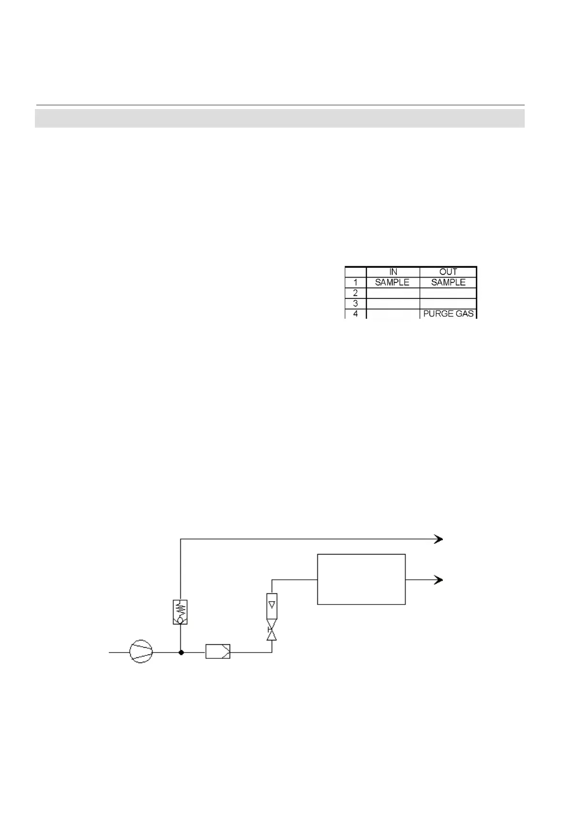
Fig. 4-3: Installation in Bypass Mode
Pressure control valve
Flow sensor
Exhaust
Exhaust
Analyzer
Sample gas pump
Filter
Fig. 4-2: Labelling of Gas Connectors (example)
The analyzer should be mounted close to the
sample gas source to minimize transport time.
A sample gas pump can be used to reduce the
reaction time; this requires that the analyzer
be operated in bypass mode or tted with
a pressure control valve to protect against
excessive gas ow and pressure (Fig. 4-3).
4.4 Installation - Gas Connections
Should it be necessary to open the gas lines,
the gas connectors should be sealed with
PVC caps to prevent pollution by moisture,
dust, etc.

 Loading...