Home
Emerson
Measuring Instruments
X-STREAM XE
Emerson X-STREAM XE User Manual
4
of 1
of 1 rating
536 pages
Give review
Manual
Specs
To Next Page
To Next Page
To Previous Page
To Previous Page
Loading...
Emerson Process Management GmbH & Co. OHG
2-6
X-STREAM XE
Instruction Manual
HASXEE-IM-HS
10/2012
2.2.1 Model-S
pecic
T
echnical Data: X-STREAM XEGK
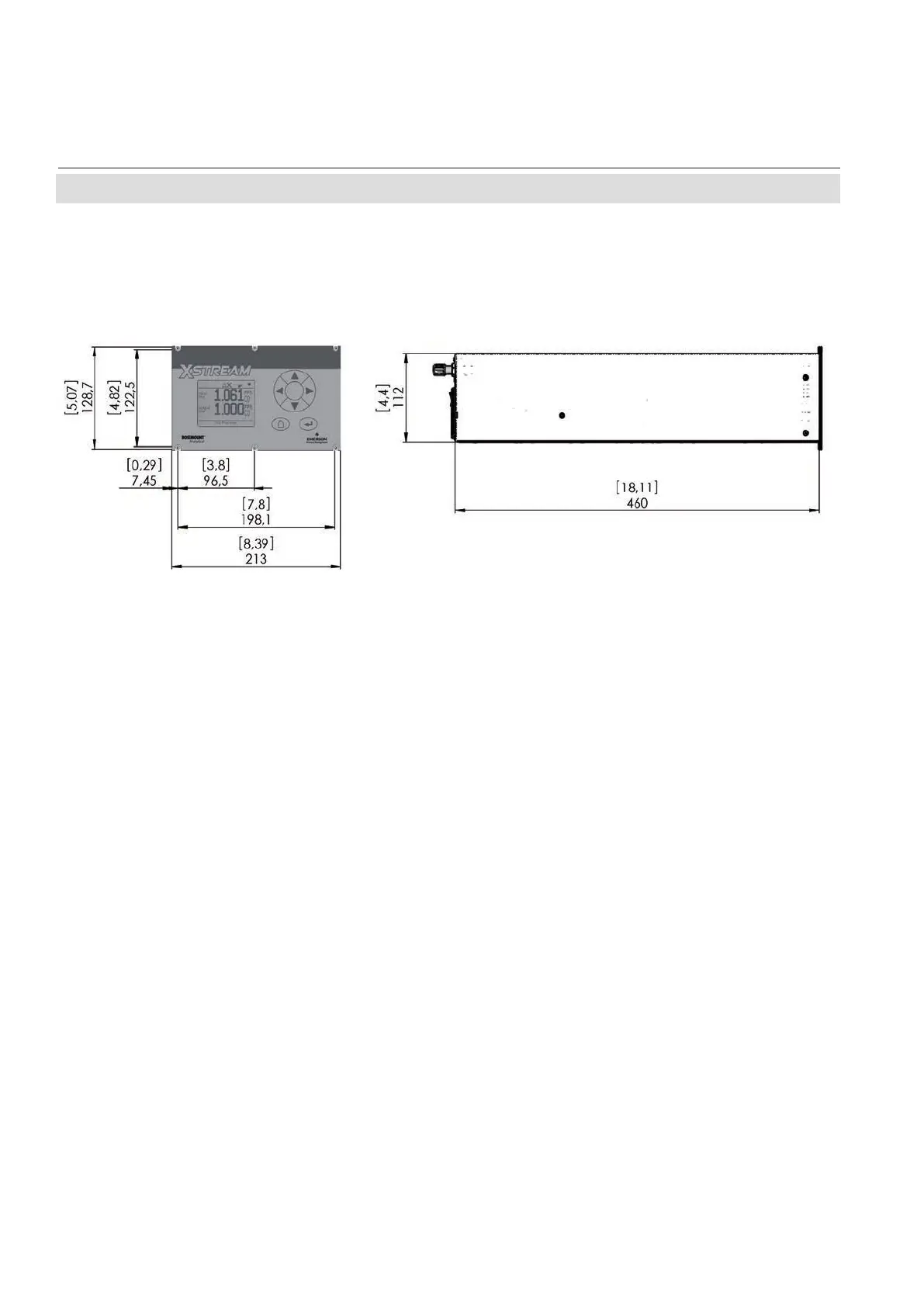
Fig. 2-1:
X-STREAM XEGK - Dimensions
2.2
Model-S
pecic
T
echnical Data
2.2.1
X-STREAM XEGK: ½19 Inch T
abletop Unit
All dimensions in mm [in]
57
59
Table of Contents
Default Chapter
4
Table of Contents
4
Introduction
13
Maintenance Procedures
13
Terms Used in this Instruction Manual
14
Symbols Used on and Inside the Unit
15
Symbols Used in this Manual
16
Additional Literature
17
General Safety Notice / Residual Risk
17
Intended Use Statement
17
Definitions
13
Safety Instructions
17
Authorized Personnel
18
Notes on Batteries
18
Installing and Connecting the Unit
19
Operating and Maintaining this Unit
19
Chapter 1 Technical Description
25
Overview
28
The Front Panel
28
Fig. 1-1: X-STREAM Enhanced Front Panel (here X-STREAM XEGP)
28
Configuration of Gas Lines
29
Materials Used
29
Safety Filter
29
Gas Inlets and Outlets
29
Tubing
29
Infallible Containments
29
Optional Components for Gas Lines
30
Fig. 1-2: Optional Heated Area
32
Fig. 1-3: Suppressed Ranges Options
33
Configurations
34
Fig. 1-4: Gas Flow Diagram: Single Channel or in Series
34
Interfaces
35
Analog Outputs
35
Status Relays
35
Modbus Interface, Ethernet
36
Serial Interface
36
USB Interfaces
36
Fig. 1-5: Ethernet Interface Marking
36
Fig. 1-6: Serial Interface Marking
36
Fig. 1-7: USB Interfaces
36
Optional Interfaces
37
Comparison of the Various X-STREAM Enhanced Analyzer Models
38
X-STREAM XEGK: ½19 Inch Table-Top Unit
40
Fig. 1-8: X-STREAM XEGK - Views
41
Fig. 8-3: X-STREAM XEGK
41
X-STREAM XEGP: 19 Inch Table-Top or Rackmount Design
42
Fig. 1-9: X-STREAM XEGP - Details
43
X-STREAM XEXF: Field Housing with (XEF ) Single or (XDF) Dual Compartment
44
Fig. 1-10: X-STREAM XEXF Field Housings- Front Views
45
Fig. 1-11: X-STREAM XEF - Right Side and Bottom View
46
Fig. 1-12: X-STREAM XEF - Power Supply and Signal Terminals
47
Field Housings XEXF for Installation in Hazardous Areas (Ex-Zones & Divisions)
48
X-STREAM XEFD: Cast Aluminum Flameproof Housing
49
Fig. 1-13: X-STREAM XEFD - Front View
50
Fig. 1-14: X-STREAM XEFD - Bottom View
51
Fig. 1-15: X-STREAM XEFD - Terminals
52
Chapter 2 Technical Data
53
Common Technical Data
53
Model-Specific Technical Data
58
X-STREAM XEGK: ½19 Inch Tabletop Unit
58
Fig. 2-1: X-STREAM XEGK - Dimensions
58
Fig. 2-2: X-STREAM XEGK - Rear Panel and Handle Variations
59
Fig. 2-3: UPS 01 Tabletop Power Supply Unit
61
Fig. 2-4: UPS 01 Power Supply Unit for Rack Installation
62
Fig. 2-5: 10 a Tabletop PSU
63
X-STREAM XEGP: 19 Inch Tabletop and Rack-Mount Models
64
Fig. 2-6: X-STREAM XEGP - Dimensions
64
Fig. 2-7: X-STREAM XEGP - Power Supply and Signal Connections
66
X-STREAM XEXF: Field Housing with (XEF) Single or (XDF) Dual Compartment
67
Fig. 2-9: X-STREAM XEF - Dimensions
67
Fig. 2-10: X-STREAM XDF - Dimensions
68
Fig. 2-11: X-STREAM XEXF Field Housings - Power Supply Terminals / Fuse Holders
70
Fig. 2-12: X-STREAM XEXF Field Housings - Signal Terminals
70
X-STREAM XEFD: Flameproof Housing
71
Fig. 2-13: X-STREAM XEFD - Dimensions
71
Fig. 2-14: X-STREAM XEFD - Power Supply Terminals / Fuse Holders
73
Fig. 2-15: X-STREAM XEFD - Signal Terminals
73
Information on Name Plate
74
Fig. 2-16: Analyzer Name Plate (Examples)
74
Chapter 3 Measuring Principles
75
Infrared Measurement (IR), Ultraviolet Measurement (UV)
75
Intrinzx Technology
75
Fig. 3-1: Intrinzx Signal Forms
76
NDIR Detector
77
Technical Implementation
78
Fig. 3-3: Photometer Assembly Principle
78
Oxygen Measurement
79
Paramagnetic Measurement
79
Fig. 3-4: Paramagnetic Oxygen Sensor - Assembly Principle
79
Tab. 3-1: Paramagnetic Sensor - Cross Interferences (Examples)
80
Tab. 3-2: Solvent Resistant Paramagnetic Sensor - Approved Solvents
81
Tab. 3-3: Paramagnetic Sensor - Medium Affected Materials
81
Electrochemical Measurement
82
Fig. 3-5: Electrochemical O Sensor - Design Principle
82
Fig. 33-6:6: Electrochemical O Sensor 3-6: Assembly
82
Fig. 3-7: Electrochemical Reaction of Oxygen Sensor
83
Fig. 3-8: Cover for EO2 Sensor Block at Rear Panel
84
Electrochemical Trace Oxygen Measurement
85
Fig. 3-9: Trace Oxygen Sensor Design Principle
85
Fig. 3-10: Cover for TO2 Sensor Block at Rear Panel
86
Thermal Conductivity Measurement
87
Principle of Operation
87
Fig. 3-11: Wheatstone Bridge
87
Tab. 3-5: Examples of Specific Thermal Conductivities
87
Technical Implementation
88
Fig. 3-12: TC Cell, Exterior View, Thermal Isolation Removed
88
Fig. 3-13: TC Cell, Sectional View
88
Trace Moisture Measurement
89
Fig. 3-14: Trace Moisture Sensor Assembly
89
Special Operating Conditions
90
Tab. 3-6: Dew Points and Water Content (at 1013 Hpa)
90
Accompanying Gases
91
Tab. 3-7: Limitations on Gases
91
Measurement Specifications
95
Chapter 4 Installation
101
Scope of Supply
101
Fig. 4-1: X-STREAM Enhanced Analyzers - Scope of Supply
101
Introduction
102
Gas Conditioning
103
Gas Connections
105
Fig. 4-3: Installation in Bypass Mode
106
Fig. 4-2: Labelling of Gas Connectors (Example)
106
Electrical Connections
107
Analyzer Specific Instructions for Installation
108
X-Stream Xegk, X-Stream Xegp
109
Fig. 4-4: X-STREAM XEGK - Rack Mount Version Rear Panel
109
Fig. 4-5: X-STREAM XEGP - Table Top Version Rear Panel
110
Fig. 4-7: Socket X1 - Analog & Digital Outputs 1–4
112
Fig. 4-8: Plug X2 - Serial Interface
113
Fig. 4-9: Configuration of XSTA Terminal Adapter
114
Fig. 4-10: Sockets X4.1 and X4.2 - Pin Configuration
115
Fig. 4-11: Configuration of XSTD Terminal Adapter
116
Fig. 4-12: Plug X5 - Analog Inputs
117
Fig. 4-13: Configuration of XSTI Terminal Adapter
118
Fig. 4-14: Power Supply Connectors
119
X-STREAM XEXF (Single XEF; Dual XDF)
120
Fig. 4-15: X-STREAM XEF - Dimensions for Installation
120
Fig. 4-16: X-STREAM XDF - Dimensions for Installation
121
Fig. 4-17: X-STREAM XEXF Field Housings - Terminals, Cable Glands and Gas Fittings
122
Fig. 4-18: Terminal Block X1 - Analog Signals and Relay Outputs 1-4
125
Fig. 4-19: Terminal Block X1 - Serial Interface
126
Fig. 4-20: Ethernet Connector
127
Fig. 4-21: X4: Terminal Blocks for Digital Inputs and Outputs
128
Fig. 4-22: Terminal Block X5 - Analog Input Signals
129
Fig. 4-23: Power Supply Connections
130
Notes on Wiring Signal Inputs and Outputs
132
Electrical Shielding of Cables
132
Fig. 4-24: Shielded Signal Cable, Shielding Connected at both Ends
132
Fig. 4-25: Shielded Signal Cable, Shielding Connected at One End
133
Fig. 4-26: Signal Cable with Double Shielding, Shieldings Connected at Alternate Ends
133
Fig. 4-27: Shield Connector Terminal with Cable
134
Wiring Inductive Loads
135
Driving High-Current Loads
135
Fig. 4-28: Suppressor Diode for Inductive Loads
135
Fig. 4-29: Driving High-Current Loads
135
Driving Multiple Loads
136
Fig. 4-30: Common Line
136
Fig. 4-31: Loads in Parallel
136
Chapter 5 Startup
137
Introduction
137
Symbols and Typographical Conventions
138
Front Panel Elements
139
Display
139
Status Line and Text Message Line
139
Fig. 5-1: X-STREAM Enhanced Front Panel
139
Keys
140
Software
142
Access Levels & Codes
145
Special Messages
146
Powering up
146
Boot Sequence
146
Measurement Display
146
Selecting the Language
148
Checking the Settings
149
Installed Options
150
Configuring the Display
151
Calibration Setup
152
Setting the Analog Outputs
154
Tab. 5-1: Analog Output Signals Settings and Operation Modes
157
Setting Concentration Alarms
159
Fig. 5-2: Arrangement of Concentration Thresholds
159
Backup the Settings
160
Perform a Calibration
162
Chapter 6 User Interface and Software Menus
163
Symbols and Typographical Conventions
163
Menu System
164
Fig. 6-1: X-STREAM Enhanced Software Menu Structure
164
Switching on
166
Service Information
166
Control Menu
167
Fig. 6-2: Measurement Display Elements
187
Fig. 6-3: Usage of Labels and Tags
193
Setup Menu
194
Tab. 6-1: Analog Output Signals
225
Tab. 6-2: Analog Output Failure Modes
227
Tab. 6-3: Digital Output Signals
231
Tab. 6-4: Digital Input Signals
234
Fig. 6-5: USB File System Structure
266
Status Menu
270
Info Menu
284
Service Menu
288
Chapter 7 Maintenance and Other Procedures
289
Introduction
289
General Maintenance Information
290
Performing a Leak Test
292
Calibration Procedures
293
Preparing Calibrations
294
Fig. 7-2: Calibration Improvement by Variable Valve Assignments
298
Fig. 7-3: Internal Valves Assignments
300
Advanced Calibration
306
Manual Calibration
306
Fig. 7-4: Zero All Calibration Procedure Flow Diagram
312
Fig. 7-5: Span All Calibration Procedure Flow Diagram
315
Fig. 7-6: Zero&Span All Calibration Procedure Flow Diagram
317
Remote Calibration
324
Fig. 7-7: Digital Inputs - Examples of Sequences
325
Unattended Automatic Calibration
328
Fig. 7-8: Graphical Explanation of Interval Time Settings
328
Verifying a Calibration
330
Restoring a Calibration
331
Cancelling an Ongoing Calibration
331
Cross Interference Compensation
332
Replacing Worn out Sensors
337
Safety Instructions
337
Opening X-STREAM Analyzers
338
Fig. 7-9: X-STREAM XEGP
338
Fig. 7-10: X-STREAM XEGK
338
Fig. 7-11: X-STREAM XEXF Field Housings and XEFD - How to Open
339
Replacing the Electrochemical Oxygen-Sensor
341
Fig. 7-12: Location of the EO
344
Fig. 7-13: Sensor Unit Design
345
Fig. 7-14: Sensor at Rear Panel
346
Fig. 7-15: OXS Board, Top View
346
Replacing the Trace Oxygen Sensor
348
Replacing the Trace Moisture Sensor
349
Fig. 7-16: Trace Moisture Sensor Assembly Separated
349
Cleaning the Instrument´s Outside
350
Save / Restore Configuration Data Sets
351
Local Backup - Save
351
Fig. 7-17: Relations of Supported Data Sets, and Where to Find Further Information
352
Local Backup - Restore
354
Factory Defaults - Restore
355
USB Backup
356
Fig. 7-18: USB File System Structure
356
Undo Restore
360
Handling Log Files
361
Configuring Log Files
361
Exporting Log Files
362
Fig. 7-19: Subdirectory for Log Files
363
Log Files Content
364
Fig. 7-20: Example of Log File
364
Files on USB Memory Device
365
Autorun.inf
365
Xe_Win_Tools.zip
365
Fig. 7-21: USB File System Structure
365
Fig. 7-22: Autorun.inf Template
365
Web Browser
367
Connection Via Network
367
Fig. 7-23: Ethernet Connectors
367
Connection to Single Computer
368
Web Browser
368
Fig. 7-24: Web Browser Logon Screen
369
Fig. 7-25: Web Browser Measurements Screen
369
Chapter 8 Troubleshooting
371
Abstract
371
Analyzer Related NAMUR Messages
371
Channel Related Messages (Preceded by Channel Tag, E.g. CO2.1)
371
Fig. 8-1: X-STREAM XEF, XDF and XEFD, Opened with Visible Front Panel
382
Solving Problems Not Indicated by Status Messages
382
Sample Pump: Replacement of Diaphragm
388
Troubleshooting on Components
388
Fig. 8-2: X-STREAM XEGP
390
Opening X-STREAM Analyzers
390
Fig. 8-4: X-STREAM XEXF Field Housings and XEFD - How to Open
392
Fig. 8-5: XSP - Allocation of Signal Connectors
393
Signal Connectors on XSP Board
393
Paramagnetic Oxygen Cell for Standard Applications: Adjustment of Physical Zero
405
Thermal Conductivity Cell: Adjustment of Output Signal
408
Chapter 9 Modbus Functions
415
Abstract
415
Modbus TCP/IP
415
Supported Functions
415
List of Parameters and Registers - Sorted by Tag Name
417
List of Parameters and Registers - Sorted by Daniel Registers
449
Chapter 10 Service Information
479
Return of Material
479
Customer Service
480
Training
480
Chapter 11 Dismounting and Disposal
481
Dismounting and Diposal of the Analyzer
481
Appendix
483
Modbus Specification
484
EC Declaration of Conformity
494
CSA Certificate of Compliance
496
Block Diagram
503
Water Vapor: Relationship of Dewpoint, Vol.-% and G/Nm³
517
Declaration of Decontamination
518
PLC Quick Reference
519
Assignment of Terminals and Sockets
527
Tabletop & Rack Mount Analyzers
527
Field Housings
528
Index
529
4
Based on 1 rating
Ask a question
Give review
Questions and Answers:
Need help?
Do you have a question about the Emerson X-STREAM XE and is the answer not in the manual?
Ask a question
Emerson X-STREAM XE Specifications
General
Brand
Emerson
Model
X-STREAM XE
Category
Measuring Instruments
Language
English
Related product manuals
Emerson ROSEMOUNT X-STREAM XEXF
536 pages
Emerson ROSEMOUNT X-STREAM XEFD
536 pages
Emerson X-STREAM Series
123 pages
Rosemount Analytical X-STREAM Enhanced Series
123 pages
Emerson Dixell XWEB300D PRO
20 pages
Emerson Rosemount Xstream Series
298 pages
ROSEMOUNT Xstream X2 Series
149 pages
Emerson AMS
78 pages
Emerson FB1100
86 pages
Emerson FB1200
114 pages
Emerson Micro Motion
76 pages
Emerson Rosemount 8800D Series
56 pages

 Loading...