Emerson Process Management GmbH & Co. OHG3-4
X-STREAM XE
Instruction Manual
HASXEE-IM-HS
10/2012
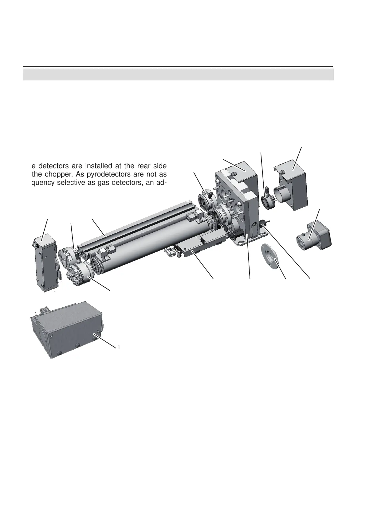
Fig. 3-3: Photometer Assembly Principle
3.1.3 Technical Implementation
3.1 Infrared (IR) and Ultraviolet (UV) Measurement
1 UV source
2 Adaptor cell
3 Analysis cell (internal view)
4 Filter cell
5 UV detector
6 Gas detector
7 IR detector electronics
8 Pyro detector (alternatively)
9 Temperature sensor
10 Filter for pyro detector assembly
11 Chopper
12 Chopper electronics
13 IR source
14 EDL
The radiation emitted by an IR or UV/EDL
source passes an adaptor cell, widening the
beam to completely ll out the analysis cell´s
diameter. At the opposite side of the cell,
another adaptor cell is installed to reduce
the beam to the diameter of the opening in
the chopper.
The detectors are installed at the rear side
of the chopper.
As pyrodetectors are not as
frequency selective as gas detectors, an ad-
ditional lter has to be installed when using
pyrodetectors, limiting the bandwidth of radi-
ation passing the chopper.
1
2
3
4
5
6
7
8
9
11 10
13
14
12

 Loading...