Emerson Process Management GmbH & Co. OHG 4-17
X-STREAM XE
Instruction Manual
HASXEE-IM-HS
10/2012
4
Installation
4.6.1 Installation - X-STREAM XEGK, X-STREAM XEGP
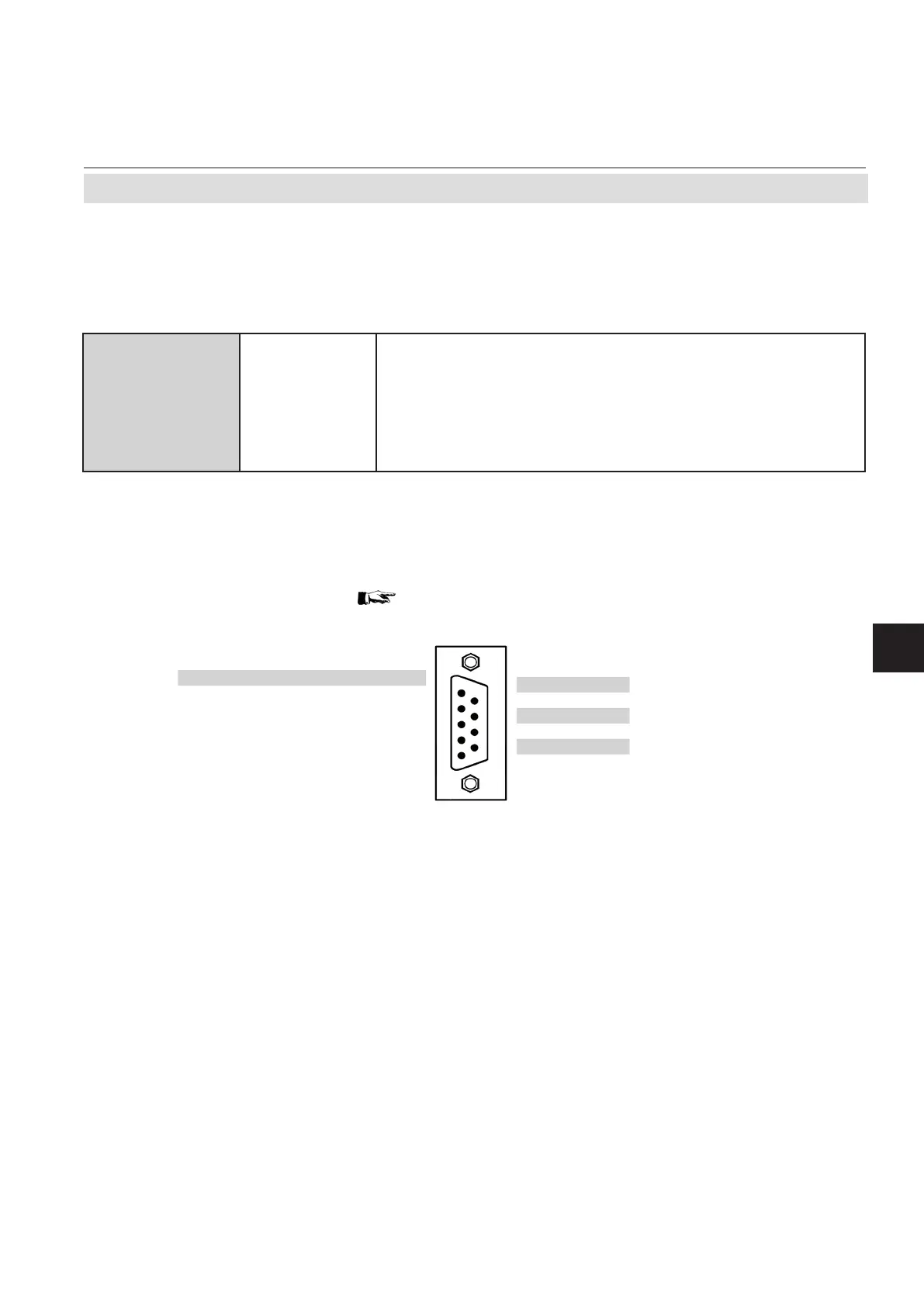
Fig. 4-12: Plug X5 - Analog Inputs
Analog inputs
Analog inputs are located on a 9-pole submin-D-connector (plug X5; Fig. 4-12) or on an optio-
nal terminals adaptor XSTI (Fig. 4-13).
Pin Signal
9 Input 2 high (+)
8 Input 2 low (-)
7 Input 1 low (-)
6 Input 1 high (+)
Signal Pin
BR 2 t a wire bridge here to apply analog
5
BR 2 signal in current mode to input 2 **)
4
unused 3
BR 1 t a wire bridge here to apply analog
2
BR 1 signal in current mode to input 1 *)
1
{ }
{ }
*) alternatively set jumper P2 on electronics board XASI
**) alternatively set jumper P1 on electronics board XASI
2 analog inputs
electrical
specication
0–1 (10) V, software selectable; R
in
= 100 kΩ
optional (requires to t wire bridges, see gures):
0–20 mA ; R
in
= 50Ω
optically isolated from analyzer GND
protected against overload up to ±
15 V or ±20 mA
Note!
Consider the installation notes in
section 4.7

 Loading...