Emerson Process Management GmbH & Co. OHG 7-57
X-STREAM XE
Instruction Manual
HASXEE-IM-HS
10/2012
7
Maintenance & Procedures
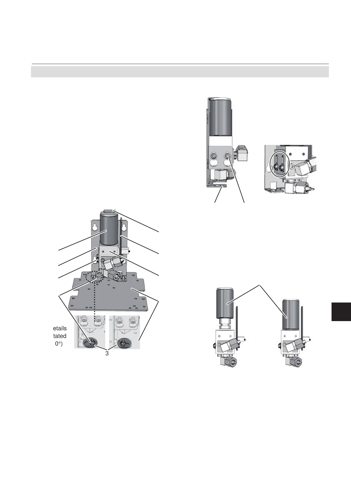
7.6.3.2 Disassembling the Sensor Unit
The sensor unit consists of a holder, an elec-
tronics board and the sensor itself, all together
installed on a base plate (Fig. 7-13).
After loosening the nut (5), push the holder
(3) with sensor (1) until the nut is above the
hole (see details), then lift the holder from the
base plate (4). The sensor is still xed in the
holder by means of a clip (8).
Now loosen the screws (7), xing the sensor
block (6) to the holder, push the holder down-
wards until the screws heads slip through the
holes.
Pull off the signal connector from the electro-
nics board (2) and take off the sensor.
Take a new sensor, remove its plug, insert the
sensor into the block and connect the signal
connector to P3 on the electronics board (Fig.
7-14).
3 7
Sensors
newweared
Now re-assemble the sensor unit in reverse
order, but do not yet install it into the analyzer
as it requires a signal adjustment.
1 Sensor
2 Electronics Board
3 Holder
4 Base Plate
5 Nuts
6 Sensor block
7 Screws
8 Clip
Fig. 7-13: Sensor Unit Design
1
3
5
7
2
6
8
4
(details
rotated
90°)
3
7.6 Replacing Worn Out Sensors

 Loading...