1-1
1. INTRODUCTION
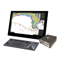
1.1 System Configuration
This ECDIS series is comprised of the components shown in the illustration on the
System Configuration page.
The Processor Unit is connected to various sensors, and performs navigation calcu-
lations, route planning and route monitoring. The Sensor Adapters interface between
the Processor Unit and external equipment.
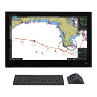
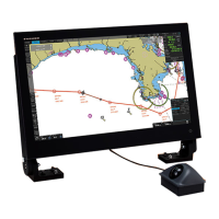
The operator controls the ECDIS with the ECDIS Control Unit RCU-024 or the Track-
ball Control Unit RCU-026. Both units are equipped with a trackball module (trackball,
right and left mouse buttons and a scrollwheel). The RCU-024 is additionally equipped
with an alphabet keyboard. All functions of the ECDIS can be accessed from the track-
ball module.
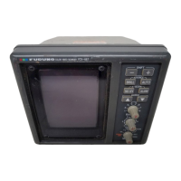
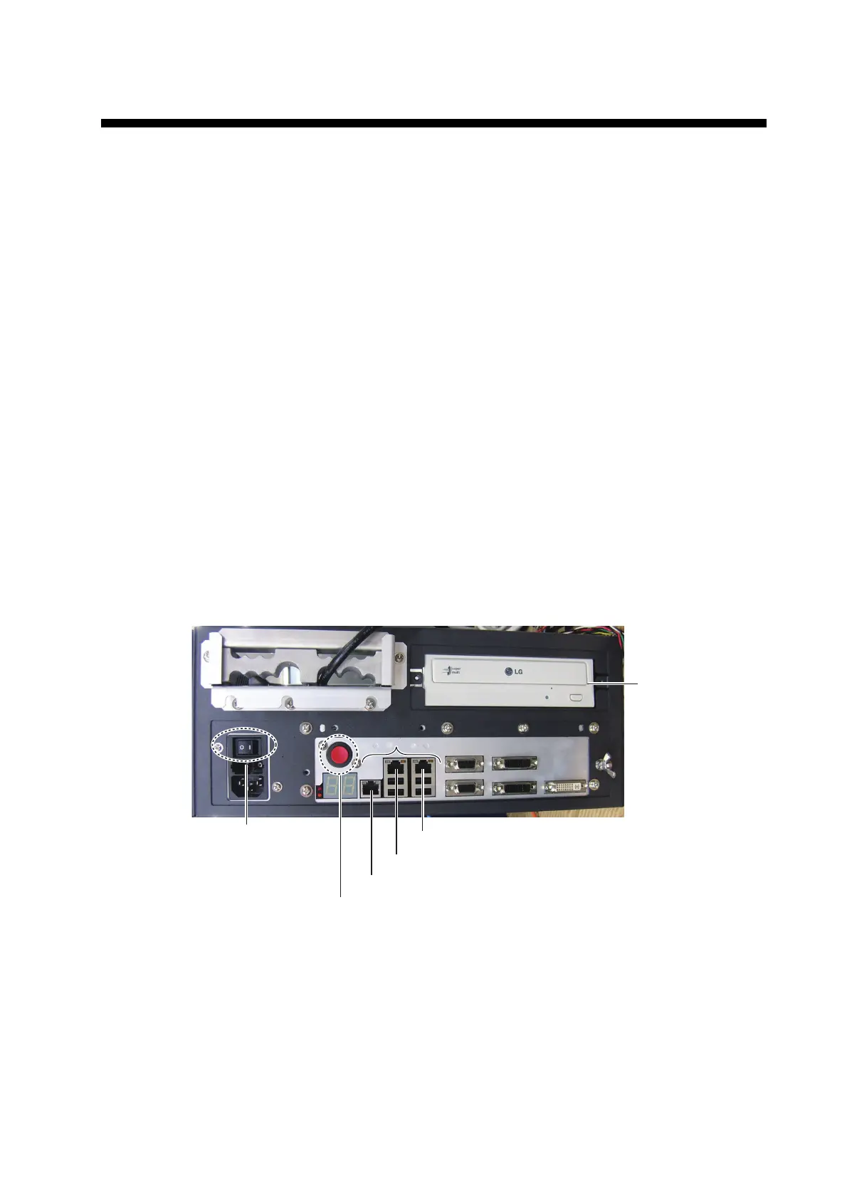
1.2 Processor Unit EC-3000
The Processor Unit is the heart of the ECDIS system, and is mainly responsible for the
chart management, route planning and route navigation.
The Processor Unit has two power switches. The Mains switch controls the power
from the switchboard, and the Power switch controls the power to the ECDIS system.
Note 1: Do not operate the system with a medium inserted in the DVD drive when its
use is not required, to prevent damage to the drive and medium. After use of a medium
is completed, remove the medium from the drive and store it in its case.
Note 2: To keep the system stable, restart the unit at least once every two weeks.
Note 3: Close the lid of the DVD drive when the drive is not in use.
Note 4: The DVD ROM provided with this equipment contains the ECDIS program.
Store the DVD in a place where the temperature and humidity are moderate. The rec-
ommended storage temperature is -10°C(14°F) to 40°C(104°F).
Power switch
Mains switch
DVD
drive
LAN1 port (Gateway network)
LAN2 port (IEC61162-450 equipment)
LAN3 port (Radar)
RJ45 NetworkRJ45 Network
 Loading...