GEK-106310AB F650 Digital Bay Controller 5-21
5 SETTINGS 5.3 SYSTEM SETUP
5
5.3SYSTEM SETUP
This section shows the settings related to the system setup definition.
5.3.1 GENERAL SETTINGS
This section determines the settings of the element configuration regarding its connection to the power system.
Access to these settings using the EnerVista 650 Setup software is at Setpoint > System Setup > General settings.
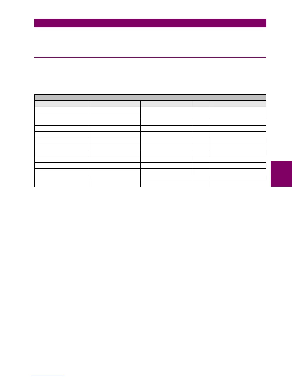
The corresponding settings are shown on the table below:
Table 5–20: GENERAL SETTINGS
The system rated voltage is used as reference by the voltage restraint in the phase timed overcurrent element.
The Frequency reference marks the voltage channel to which the system Frequency is measured.
The auxiliary voltage setting can be selected between VN and VX.
VN means that all elements using neutral voltage will take the value directly from the fourth voltage input.
VX means that all elements using neutral voltage will take the value calculated from phase voltages.
5.3.1.1 OUT OF SERVICE SETTING
The unit has the Relay Out Of Service setting only configured at the general settings element. The unit has also an Out Of
service Status that it is only configured at Relay configuration > Protection elements tab. These states act stopping all the
changes on PLC equations and functions, even stopping all the changes in the input/output boards, so if there is a change
in any of the input or output the unit will not show this change until the unit has been set again in ready mode. For example
if an output is closed and the unit goes to out of service state, the output will be kept closed even though the state, that
makes it to close, change to open the output. When the unit goes out of the out of service state the output will be opened if
it was a change.
Functions affected by Out of service State
- IO Boards.
- PROTECTIÓN:
o Generator:
• § Generator Unbalance (46 gen)
SETPOINT > SYSTEM SETUP > GENERAL SETTINGS
setting Description Name Default Value Step Range
Phase CT ratio Phase CT Ratio 1.0 0.1 [1.0 : 6000.0]
Ground CT ratio Ground CT Ratio 1.0 0.1 [1.0 : 6000.0]
Sensitive ground CT ratio Stv Ground CT Ratio 1.0 0.1 [1.0 : 6000.0]
Phase VT ratio Phase VT Ratio 1.0 0.1 [1.0 : 6000.0]
Phase VT connection Phase VT Connection WYE N/A [WYE – DELTA]
Rated voltage Nominal Voltage 100.0 0.1 [1.0 : 250.0]
Rated Frequency Nominal Frequency 50 Hz N/A [50-60]
Phase rotation Phase Rotation ABC N/A [ABC – ACB]
Frequency reference Frequency Reference VI N/A [VI-VII-VIII]
Auxiliary Voltage Auxiliary Voltage VX N/A [VX – VN]
Snapshot Event generation Snapshot Events DISABLED N/A [DISABLED – ENABLED]
Relay Out of Service Relay Out of Service ENABLED N/A [DISABLED – ENABLED]
Local/Remote Blocked Local/Remote Blocked OFF N/A [ON -OFF]

 Loading...


