5-118 F650 Digital Bay Controller GEK-106310AB
5.6 INPUTS/OUTPUTS 5 SETTINGS
5
5.6.2 CONTROL SETTINGS FOR INPUTS/OUTPUTS
Configuration of settings relative to inputs and outputs can only be accessed through the EnerVista 650 Setup
software, and not via the HMI. For this purpose, the user must access Setpoint > Inputs/Outputs > Contact I/O > Board
X, being X the corresponding I/O board.
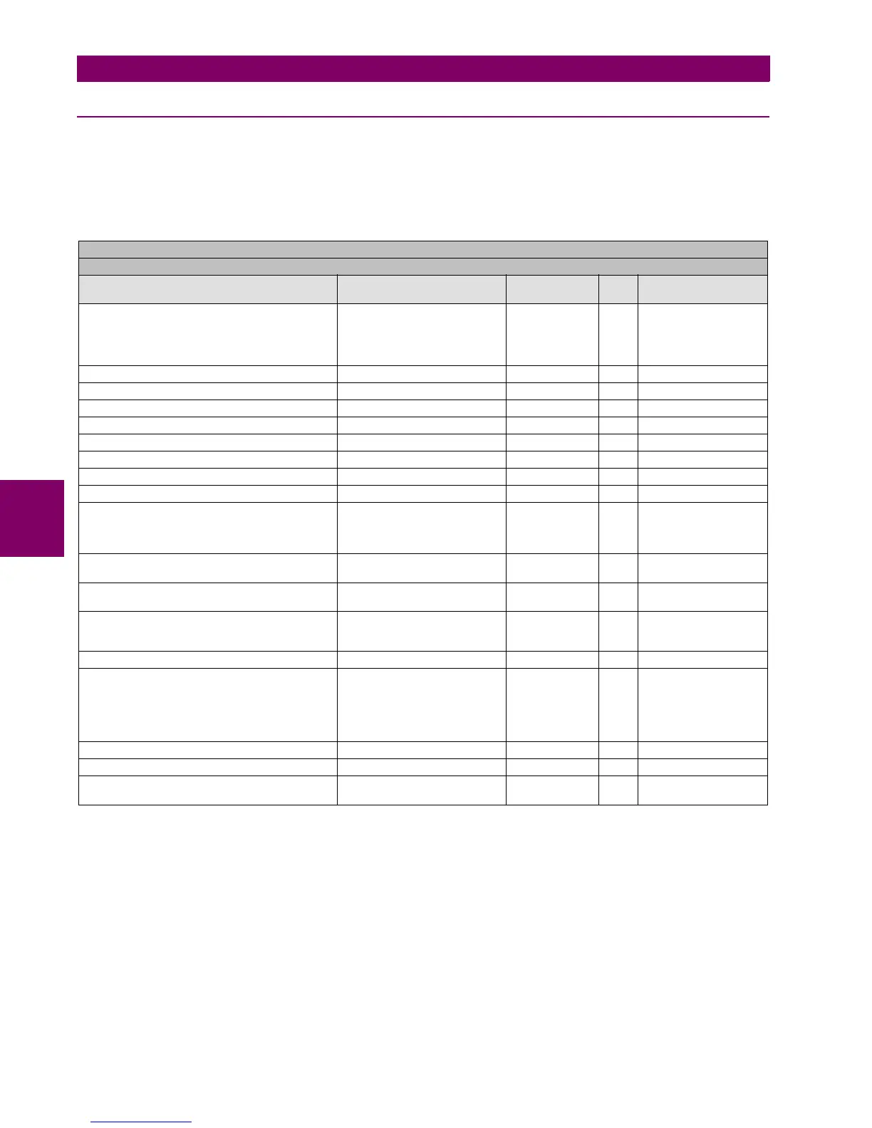
settings relative to I/O boards are described in Table 5–100:
Table 5–100: I/O BOARD SETTINGS
The snapshot event setting enables or disables the snapshot event generation for this element. It is mandatory to enable
this setting in order the input/output values to be refreshed in IEC61850 protocol
.
Being:
X F, G, H or J, the I/O board name, depending on the Relay model.
F and G are internal Relay boards, and H and J are additional boards available in CIO modules (remote Bus CAN I/O
module).
SETPOINT > INPUTS/OUTPUTS > CONTACT I/O >
BOARD F > BOARD G > BOARD H > BOARD J
SETTING DESCRIPTION NAME DEFAULT
VALUE
STEP RANGE
I/O board type (available only for CIO modules) I/O Board Type_X NONE N/A [NONE,
16 INP + 8OUT,
8 INP + 8OUT + SUPV,
32 INP
16 INP + 8 ANA]
Input activation voltage threshold Group A Voltage Threshold A_X 80 1 V [10 : 230]
Input activation voltage threshold Group B Voltage Threshold B_X 80 1 V [10 : 230]
Input activation voltage threshold Group C Voltage Threshold C_X 80 1 V [10 : 230]
Input activation voltage threshold Group D Voltage Threshold D_X 80 1 V [10 : 230]
Debounce time for Group A Debounce Time A_X 15 1 ms [1 : 50]
Debounce time for Group B Debounce Time B_X 15 1 ms [1 : 50]
Debounce time for Group C Debounce Time C_X 15 1 ms [1 : 50]
Debounce time for Group D Debounce Time D_X 15 1 ms [1 : 50]
Input type Input Type_X_CCY (CCY) POSITIVE N/A [POSITIVE-EDGE,
NEGATIVE-EDGE,
POSITIVE,
NEGATIVE]
Input signal time delay Delay Input Time_X_CCY
(CCY)
0 1 ms [0 : 60000]
Output logic type Output Logic_X_0Z POSITIVE N/A [POSITIVE,
NEGATIVE]
Output type Output Type_X_0Z NORMAL N/A [NORMAL,
PULSE,
LATCH]
Output pulse length Pulse Output Time_X_0Z 10000 1 ms [0 : 60000]
Analog Inputs Range Range_X_0Z NONE N/A [NONE,
-1 to 0mA,
0 to 1 mA,
-1 to 1 mA,
0 to 5 mA,
0 to 10 mA]
Minimum Value Min_Value_X_0Z 0.00 0.01 [ -9999.99 : 9999.99]
Maximum Value Max_Value_X_0Z 0.00 0.01 [ -9999.99 : 9999.99]
Snapshot event generation Snapshot Events ENABLED N/A [DISABLED –
ENABLED]

 Loading...


