GEK-106310AB F650 Digital Bay Controller 6-37
6 ACTUAL VALUES 6.4 INPUTS / OUTPUTS
6
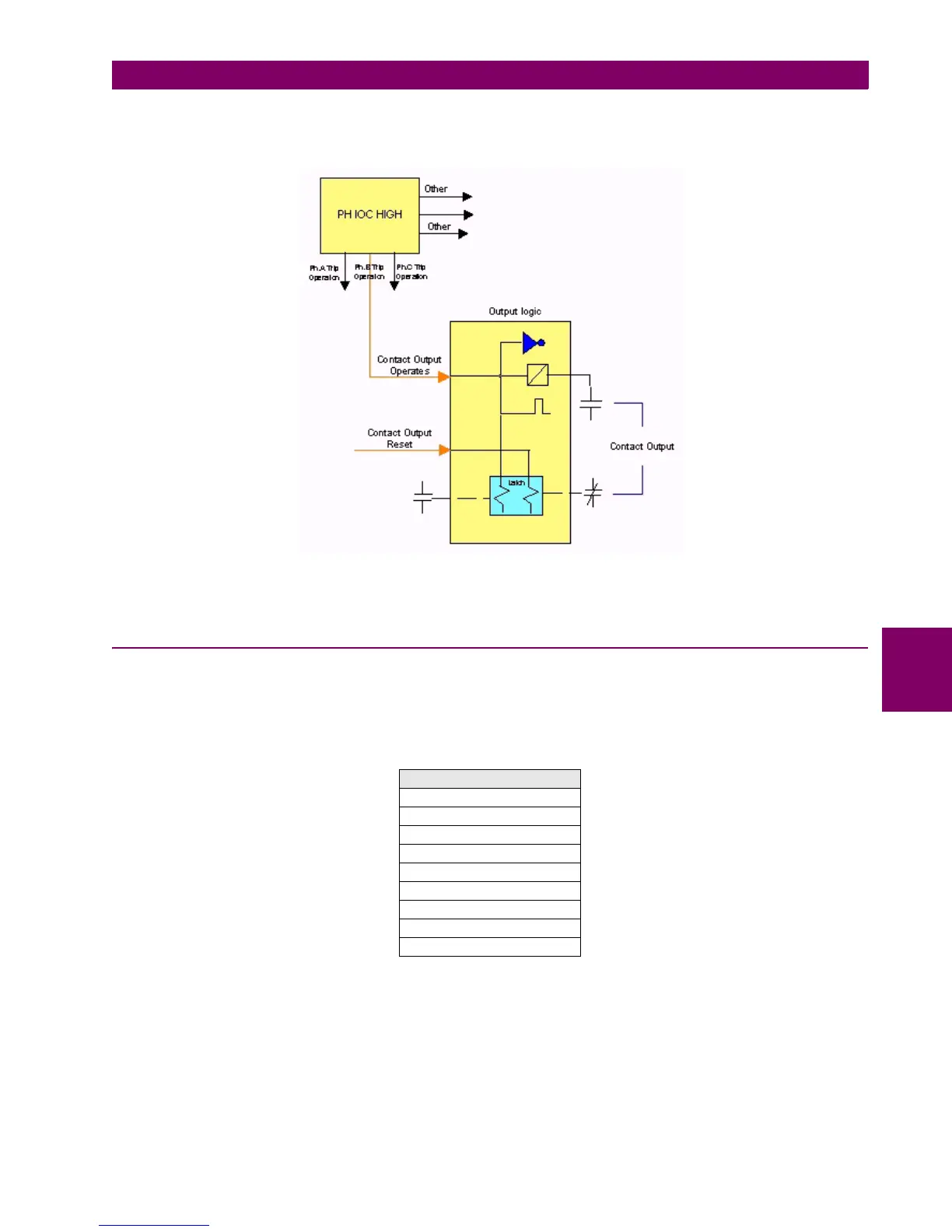
Operation example of output contacts:
Figure 6–3: OUTPUT CONTACTS OPERATION
6.4.4 CONTACT OUTPUT RESETS
Actual > Inputs/Outputs > Contact Output Resets > Board X (being X the corresponding board in each case).
Boards types 1 and 2 have both 8 outputs, so the representation is the same for both types as shown in Table 6–49:
If the reset signal is active, the green LED will light up. Otherwise, it will remain unlit.
Table 6–49: CONTACT OUTPUT RESETS
The last LED in this screen, labeled as “Board Status”, indicates the general board status.
This output reset Command will only be effective if the “latch” option has been selected for the “Output Type” setting on
the I/O board, thus when the contact output has been configured to emulate function 86 (latching relay).
Configuration for the contact output reset signal is set at Setpoint > Relay Configuration > Outputs > Contact Output
Reset.
CONTACT OUTPUT RESETS
CONT OP RESET_X_01
CONT OP RESET_X_02
CONT OP RESET_X_03
CONT OP RESET_X_04
CONT OP RESET_X_05
CONT OP RESET_X_06
CONT OP RESET_X_07
CONT OP RESET_X_08
BOARD X STATUS

 Loading...


