GEK-106310AB F650 Digital Bay Controller 6-1
6 ACTUAL VALUES 6.1 FRONT PANEL
6
6 ACTUAL VALUES 6.1FRONT PANEL
The menu bar in the main screen of EnerVista 650 Setup software shows the ACTUAL menu option. This option
concentrates and displays all status of protection, control elements, metering, counters information, oscillography, events,
fault locator, etc. This menu is divided in several submenus that will be detailed in the following sections.
6.1.1 LEDS
Operation of the relay front LEDs is shown on the following figure (Actual > Front Panel > LEDs) by the lighting of the
associated LED in the appropriate color. The Ready LED is green when the relay is in service. LEDs 1 to 5 light up in red
when active, LEDs 6 to 10 light up in orange, and the last 5 LEDs light up in green.
The first five LEDs are latched by hardware and can only be reset by a LEDs RESET Command, either pressing the “esc”
key on the Front of the Relay, or by Communications using the appropriate signal. The rest of LEDs are not latched, but can
be latched by logic.
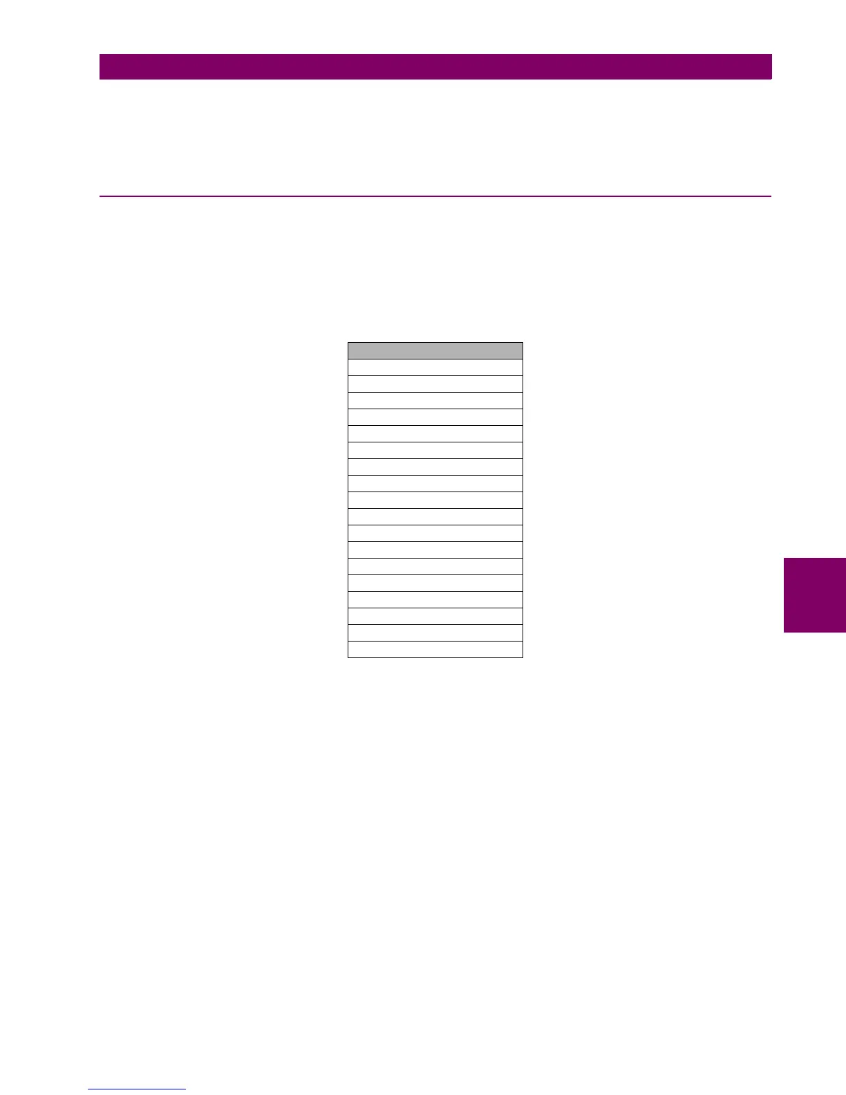
Table 6–1: FRONT PANEL LEDS
LEDS
READY LED
LED 1
LED 2
LED 3
LED 4
LED 5
LED 6
LED 7
LED 8
LED 9
LED 10
LED 11
LED 12
LED 13
LED 14
LED 15
LOCAL OPERATION MODE
OPERATIONS BLOCKED

 Loading...


