GEK-106310AB F650 Digital Bay Controller 11-5
11 APPLICATION EXAMPLES 11.2 EXAMPLE 2: TOC PROTECTION + RECLOSING SETTINGS PROCEDURE
11
11.2 EXAMPLE 2: TOC PROTECTION + RECLOSING SETTINGS PROCEDURE
11.2.1 DESCRIPTION OF THE EXERCISE
The purpose of this exercise is to introduce the F650 User about the way to set a protection scheme including:
Trip operation of a phase time overcurrent protection.
Two reclosing shots with successful fault clearing.
Synchronism check action to verify two ends voltage conditions previous to perform each reclosing action.
11.2.2 PROCEDURE TO COMMUNICATE THE RELAY
This procedure is described in Example Nº 1. Therefore check the actual PC communication status to assure a fast and
reliable communication with F650 relay.
11.2.3 PROCEDURE TO SET THE PROTECTION FUNCTION
This procedure is fully described in paragraph 13.3 (see Example Nº 1). Therefore it is not necessary to explain it here
again except about the small modifications required for the actual exercise, as well the additional settings not used until
now (i.e. recloser and synchrocheck).
Therefore, by having the F650 set like in the previous exercise (paragraph 13), the new settings and changes to be done in
the relay to work in a protection-reclosing scheme are:
Under
SETPOINT SYSTEM SETUP BREAKER BREAKER SETTINGS
Under
SETPOINT INPUTS/OUTPUTS CONTACT I/O BOARD F
Under
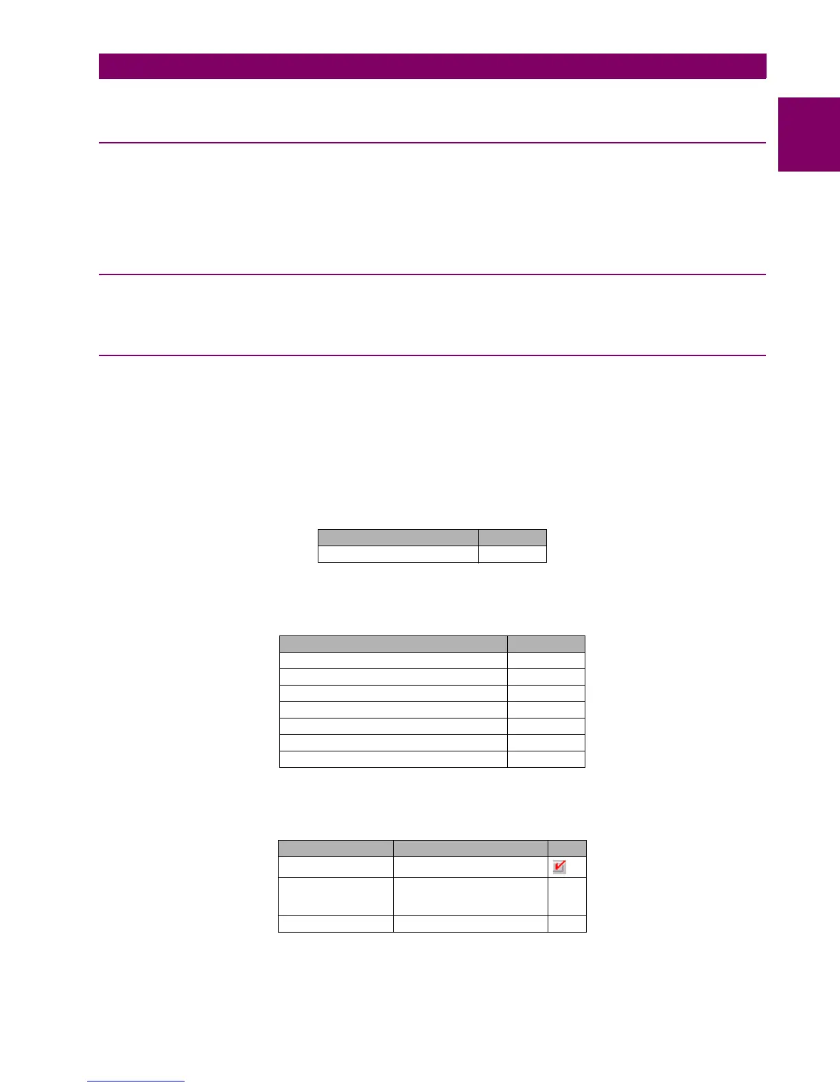
SETPOINT RELAY CONFIGURATION PROTECTION ELEMENTS
NAME VALUE
Number of Switchgear 1
NAME VALUE
Output Logic_00_00 Positive
Voltage Threshold B_00 80V
Debounce Time B_00 10 ms
Input Type_00_00 (CC1) Positive
Delay Input Time_00_00 (CC1) 0 ms
Output Type_00_00 Normal
Pulse Output Time_00_00 500 ms
SELECT SOURCE OR
AR Initiate PRESS FOR LOGIC
Phase TOC A Op
Phase TOC B Op
Phase TOC C Op
AR Conds Input Synch Close Perm

 Loading...


