GEK-106310AB F650 Digital Bay Controller 5-115
5 SETTINGS 5.5 CONTROL ELEMENTS
5
5.5.13 LOAD ENCROACHMENT
The settings can be selected at Setpoint > Control Elements > Load Encroachment
Table 5–97: LOAD ENCROACHMENT SETTINGS
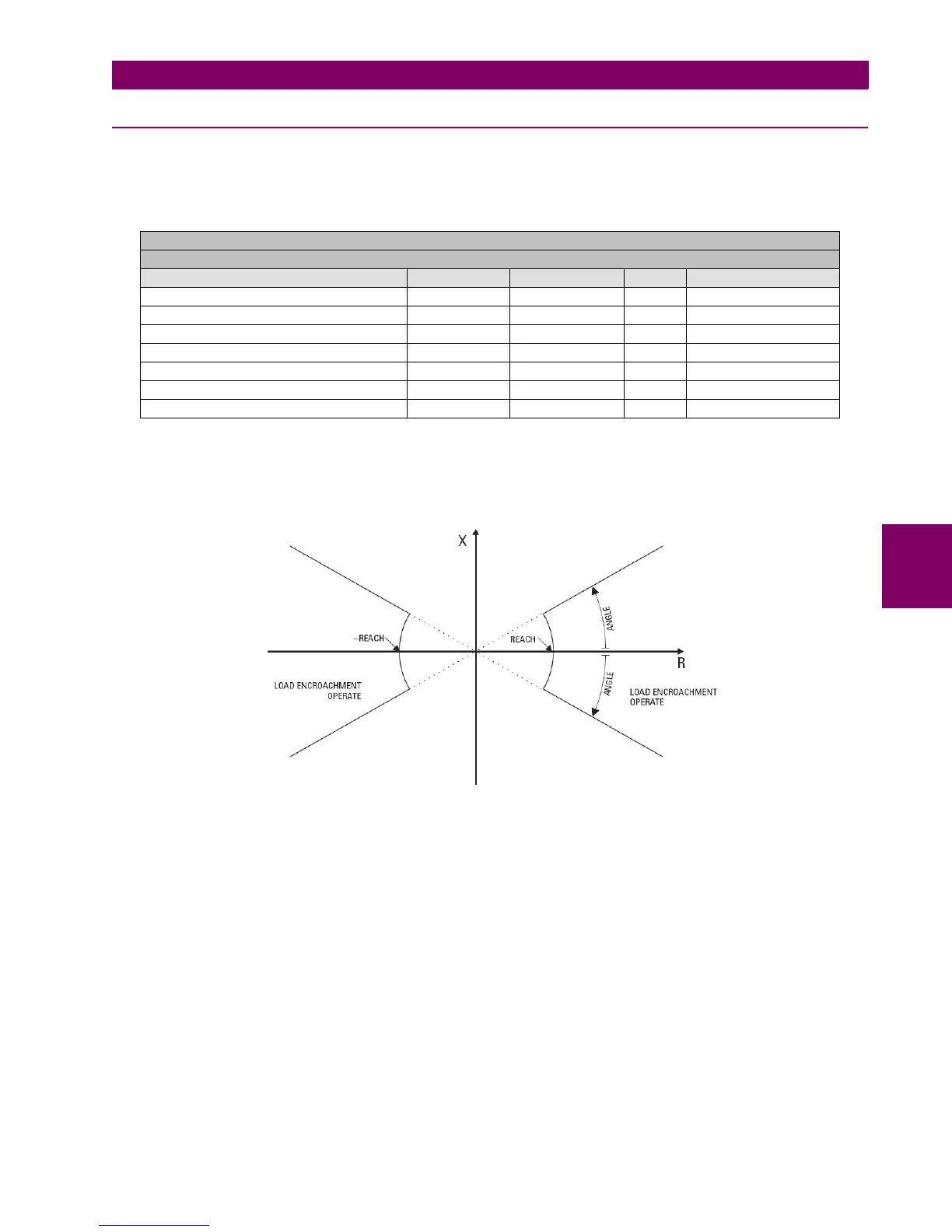
The load encroachment element responds to the positive-sequence voltage and current and applies a characteristic shown
in the figure below.
Figure 5–31: LOAD ENCROACHMENT CHARACTERISTIC
The element operates if the positive-sequence voltage is above a selectable level and asserts its output signal that can be
used to block selected protection elements such as distance or phase overcurrent.
The customer must take into account that the time programmed in the overcurrent element must be higher than the time
programmed in the load encroachment function to avoid false tripping.
Load encroachment settings description:
Load Encroachment function: enable/disable the Load Encroachment function.
Min Voltage: This setting specifies the minimum positive-sequence voltage required for operation of the element. If the
voltage is below this threshold a blocking signal will not be asserted by the element.
Reach: This setting specifies the impedance reach of the element as shown in the load encroachment characteristic
diagram. This settings should be entered in secondary ohms and be calculated as the positive-sequence impedance seen
by the relay under maximum load conditions.
SETPOINT > CONTROL ELEMENTS > LOAD ENCROACHMENT
LOAD ENCROACHMENT 1 > LOAD ENCROACHMENT 2 > LOAD ENCROACHMENT 3
SETTING DESCRIPTION NAME DEFAULT VALUE STEP RANGE
Function Permission Function DISABLED N/A [DISABLED – ENABLED]
Minimum positive-sequence voltage required Min. Voltage 25.00 0.01 V [0.00 : 300.00]
Impedance reach of the element Reach 1.00 0.01 Ohm [0.02 : 250.00]
Angle (Size of the blocking region) Angle 5 1 Deg [5 : 50]
Trip Time Pickup Delay 0.000 0.001 s [0.000 : 65.535]
Reset Time Reset Delay 0.000 0.001 s [0.000 : 65.535]
Snapshot Events Generation Snapshot Events ENABLED N/A [DISABLED – ENABLED]

 Loading...


