GEK-106310AB F650 Digital Bay Controller 10-21
10 COMMISSIONING 10.15 OVERVOLTAGE ELEMENTS (59P, 59X, 59NH, 59NL, 47)
10
10.15OVERVOLTAGE ELEMENTS (59P, 59X, 59NH, 59NL, 47) 10.15.1 59P ELEMENT
Set the relay to trip for the protection element being tested. Configure any of the outputs to be activated only by the
protection element being tested.
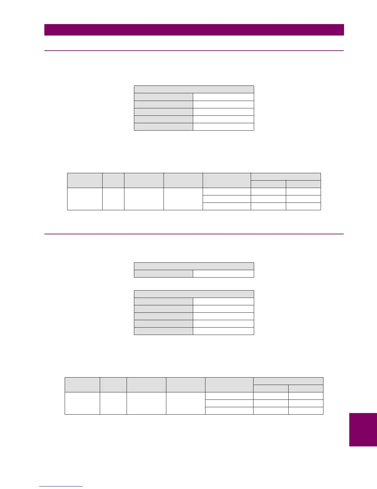
Set the relay as follows:
Apply voltage as indicated on the table under the overvoltage setting level and verify that the relay does not trip.
Verify that the relay trips for the set voltage (with an admissible error of 5%).
10.15.2 59X ELEMENT
Set the relay as follows:
Apply voltage as indicated on the table under the overvoltage setting level and verify that the relay does not trip.
Verify that the relay trips for the set voltage (with an admissible error of 5%).
PHSE OV (59P)
Function ENABLED
Pickup Level 120 V
Trip Delay 2.00
Reset Delay 0.00
Logic ANY PHASE
ELEMENT PHASE PICKUP LEVEL
(VOLTS)
TRIP DELAY
(SECONDS)
APPLIED
VOLTAGE (V)
TRIPPING TIME (S)
EXPECTED ADMISSIBLE
59P VII 120 2 114 NO TRIP NA
132 2 [1.9–2.1 ]
132 2 [1.9 – 2.1]
GENERAL SETTINGS
Auxiliary Voltage VX
AUXILIARY OV (59P)
Function ENABLED
Pickup Level 120 V
Trip Delay 2.00
Reset Delay 0.00
Logic ANY PHASE
ELEMENT INPUT PICKUP LEVEL
(VOLTS)
TRIP DELAY
(SECONDS)
APPLIED
VOLTAGE (V)
TRIPPING TIME (S)
EXPECTED ADMISSIBLE
59X VX 120 2 114 NO TRIP NA
132 2 [1.9–2.1]
132 2 [1.9 – 2.1]

 Loading...


