10-4 F650 Digital Bay Controller GEK-106310AB
10.4 ISOLATION TESTS 10 COMMISSIONING
10
10.4ISOLATION TESTS
During all tests, the screw located on the rear of the relay must be grounded.
For verifying isolation, independent groups will be created, and voltage will be applied as follows:
2200 RMS volts will be applied progressively
among all terminals in a group, short-circuited between them and the
case, during one second.
2200 RMS volts will be applied progressively between groups, during one second.
WARNING: No communication circuit shall be tested for isolation.
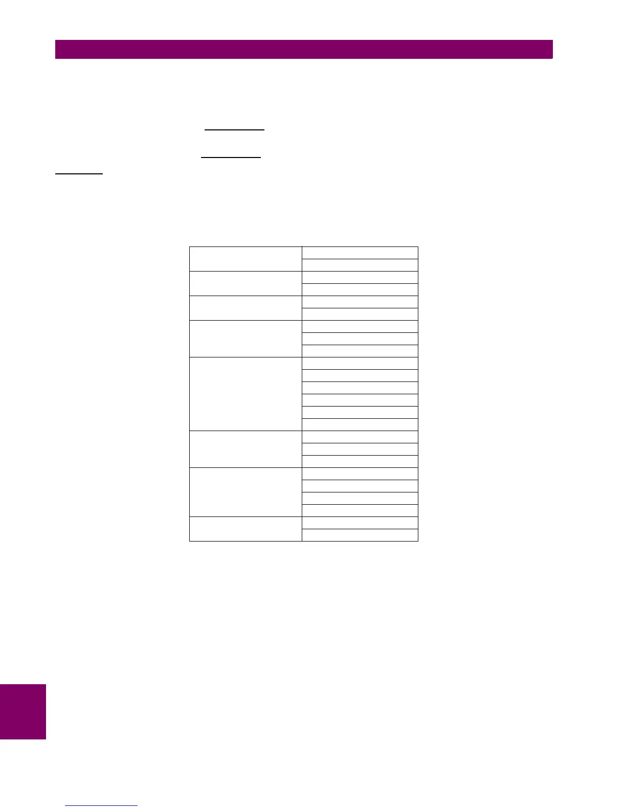
Groups to be created will depend on the type of modules included in F650, selectable according to the model.
The following table shows the different groups depending on the module type:
SOURCE 1:
G1: H10, H18
G2: H13, H14, H15
SOURCE 2:
G1: H1, H9
G2: H4, H5, H6
MAGNETIC MODULE.
G1: A5..A12
G2: B1..B12
I/O F1 (MIXED)
G1 (Inp. 1): F1..9
G2 (Inp. 2): F10..18
G3 (Out.): F19..36
I/O F2 (SUPERVISION)
G1 (Spv 1): F1..4
G2 (Inp. 1): F5..9
G3 (Inp. 2): F10..14
G4 (Spv 2): F15..18
G5 (Out.): F19..30
G6 (Out.): F31.36
I/O G1 (MIXED)
G1 (Inp. 1): G1..9
G2 (Inp. 2): G10..18
G3 (Out.): G19..36
I/O G4 (32DI)
G1 (Inp. 1): G1..9
G2 (Inp. 2): G10..18
G3 (Inp. 3): G19..28
G4 (Inp. 3): G29..36
I/O G5 (ANALOG)
G1 (Inp. 1): G1..9
G2 (Inp. 2): G10..18

 Loading...


