GEK-106310AB F650 Digital Bay Controller 5-109
5 SETTINGS 5.5 CONTROL ELEMENTS
5
The Operation Threshold level has been included to allow the user selecting the current inhibition level suitable for a
particular application, in order to avoid operation of the element when the relay is not connected to the line or in case the
relay has previously operated correctly and has been disconnected from the line, as in this case the operation condition is
met but the relay should not trip.
The operation threshold operation is as follows:
The Broken conductor element will be fully operational if at least one of the phase currents is higher than the setting. This
condition assumes that the relay is connected to the line.
If the element is on trip or pickup condition, the element will be reset if the three phase currents are below the operation
threshold level. This condition assumes that the relay is not connected to the line and therefore the relay should not trip.
Due to the response time of this function, if the set time delay is 0s, a trip could occur in situations where, for example, one
of the currents is stopped before the rest, as these currents would produce a negative sequence current calculation.
Therefore, to avoid this kind of undesired trips, it is strongly recommended to establish a minimum time delay setting, such
as 100 ms, or higher depending on the expected normal unbalances in the network. This is to differentiate these situations
from broken conductor situations.
5.5.9 LOCKED ROTOR
F650 incorporates a locked rotor element with three elements. Protection element 48 produces a trip when current
(primary values) exceeds the set value. This current setting value is the product of the set Full load current by the pickup
setting.
Setpoint > Control Elements > Locked Rotor
Table 5–87: LOCKED ROTOR ELEMENT SETTINGS
Locked rotor element settings are:
Function Permission (Function): This setting indicates whether the locked rotor element is enabled or disabled.
Input (Phasor(DFT)-RMS): Selection between fundamental phasor magnitude (DFT) or total waveform RMS
magnitude.
Full Load Current (FLC): This is the average maximum expected operating phase current for the motor.
Pickup Level: This is the current threshold over the full load current setting with which the element
will operate. The operating current for this element is calculated as follows:
Trip time (Trip Delay): Setting of the Protection element operation time.
Reset time (Reset Delay): Reset time of the Protection element.
Snapshot Events: The snapshot event setting enables or disables the snapshot event generation for
this element.
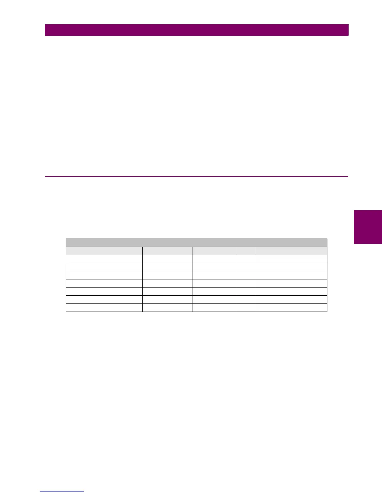
SETPOINT > CONTROL ELEMENTS > LOCKED ROTOR
SETTING DESCRIPTION NAME DEFAULT VALUE STEP RANGE
Function permission Function DISABLED N/A [DISABLED – ENABLED]
Input type Input PHASOR (DFT) N/A [PHASOR – RMS]
Full load current Full Load Current 0.50 KA [0.10 : 10.00]
Pickup level Pickup Level 1.01 N/A [1.01 : 109.00]
Trip time Trip Delay 0.00 s [0.00 : 900.00]
Reset time Reset Delay 0.00 s [0.00 : 900.00]
Snapshot event generation Snapshot Events ENABLED N/A [DISABLED – ENABLED]
×=

 Loading...


