6-22 F650 Digital Bay Controller GEK-106310AB
6.2 STATUS 6 ACTUAL VALUES
6
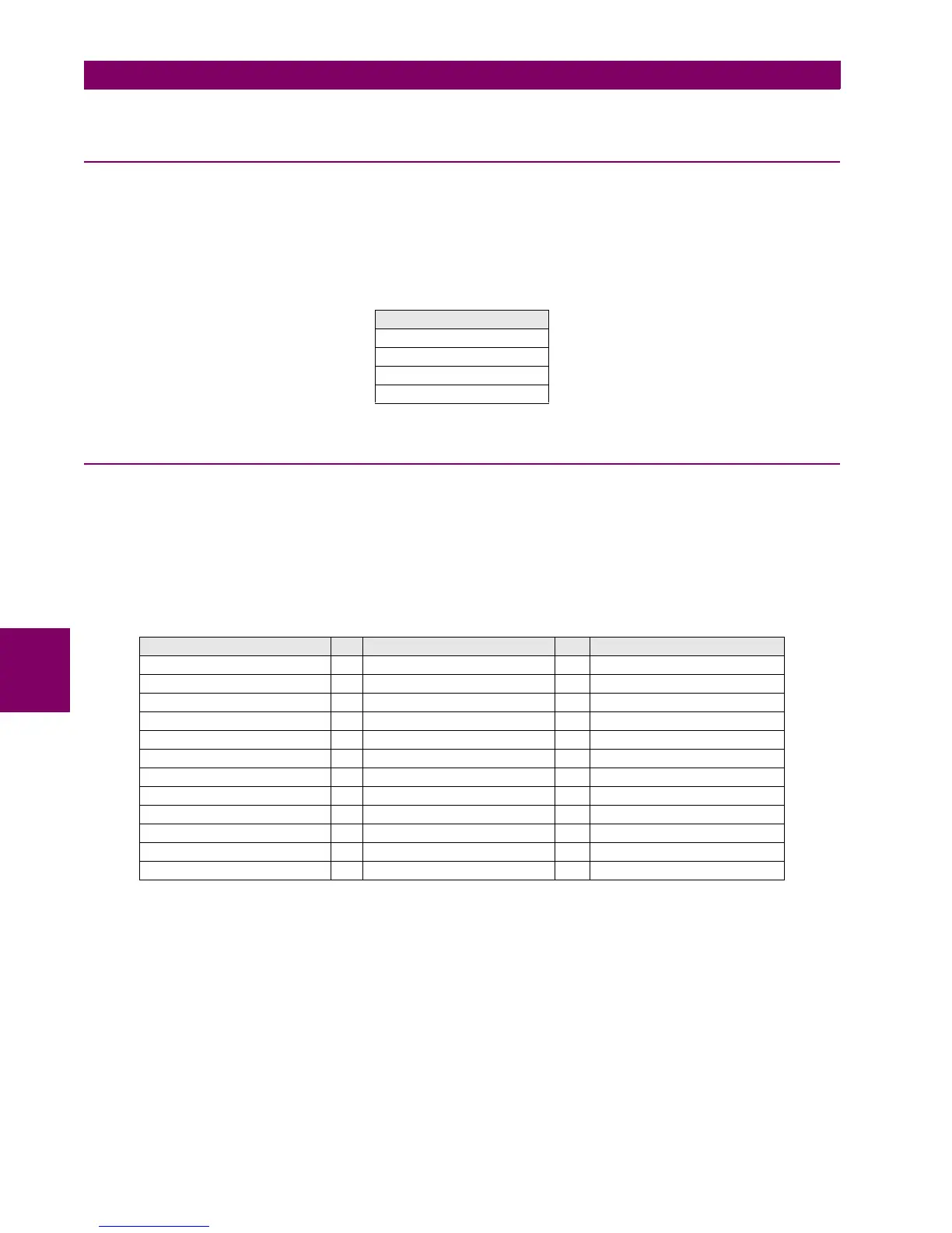
6.2.7 MODBUS USER MAP
The ModBus User Map consists of a selection of the most important 256 records in the complete ModBus Map regarding
the application. By selecting these records and defining the user map appropriately, it is possible to read all the information
included by a single ModBus reading operation, optimizing the refresh time.
This screen can be accessed at Actual> Status> ModBus User Map, and it includes all the readings for the previously
configured records in the ModBus memory map.
Table 6–26: MODBUS USER MAP ACTUAL VALUES
6.2.8 SWITCHGEAR STATUS
Actual > Status > Switchgear Status
For a better understanding of the represented statuses in this screen, figure 6.1 shows the available “Switchgear” modules
to be programmed in the F650. Each of them has a series of inputs/outputs that are the statuses represented on this
screen. Separate signal for each switchgear device (for 1 to 16).
Each Switchgear module can be programmed at: Setpoint > Relay Configuration >Switchgear, and its statuses are as
follows:
Table 6–27: SWITCHGEAR STATUS
SWITCH X A INPUT The LED will light up when the input associated to that switchgear Contact A is activated.
SWITCH X B INPUT The LED will light up when the input associated to that switchgear Contact B is activated.
SWITCH X A STATUS Status associated to Switchgear contact A. It is activated once the time required for the
Switchgear module to acknowledge contact A has expired.
SWITCH X B STATUS Status associated to Switchgear contact B. It is activated once the time required for the
Switchgear module to acknowledge contact B has expired.
SWITCH X OPEN Lights up when the associated switchgear is open
SWITCH X CLOSED Lights up when the associated switchgear is closed
SWITCH X 00_ERROR Output that represents the Switchgear status 00, considered as abnormal.
MODBUS USER MAP
Address 00
Address 01
…
Address 255
SWITCHGEAR 1 STATUS SWITCHGEAR X STATUS SWITCHGEAR 16 STATUS
SWITCH 1 A INPUT … SWITCH X A INPUT … SWITCH 16 A INPUT
SWITCH 1 B INPUT … SWITCH X B INPUT … SWITCH 16 B INPUT
SWITCH 1 A STATUS … SWITCH X A STATUS … SWITCH 16 A STATUS
SWITCH 1 B STATUS … SWITCH X B STATUS … SWITCH 16 B STATUS
SWITCH 1 OPEN … SWITCH X OPEN … SWITCH 16 OPEN
SWITCH 1 CLOSED … SWITCH X CLOSED … SWITCH 16 CLOSED
SWITCH 1 00_ERROR … SWITCH X 00_ERROR … SWITCH 16 00_ERROR
SWITCH 1 11_ERROR … SWITCH X 11_ERROR … SWITCH 16 11_ERROR
SWITCH 1 OPEN INIT … SWITCH X OPEN INIT … SWITCH 16 OPEN INIT
SWITCH 1 CLOSE INIT … SWITCH X CLOSE INIT … SWITCH 16 CLOSE INIT
SWGR 1 FAIL TO OPEN … SWGR X FAIL TO OPEN … SWGR 16 FAIL TO OPEN
SWGR 1 FAIL TO CLOSE … SWGR X FAIL TO CLOSE … SWGR 16 FAIL TO CLOSE

 Loading...


