EasyManua.ls Logo

GE F650 User Manual

GE F650
801 pages
To Next Page IconTo Next Page
To Previous Page IconTo Previous Page
Page #308 background imageLoading...
Page #308 background image
GEK-106310AB F650 Digital Bay Controller 5-161
5 SETTINGS 5.10 LOGIC CONFIGURATION (PLC EDITOR)
5
Users can build their own libraries and distribute them in their projects in an easy way.
The manufacturer provides default libraries such as ORs, ANDs of 3 up to 8 inputs, besides timers (pickup-dropout) and
key examples.
5.10.5 GENERATION OF LIBRARIES
Libraries can contain a set of operations grouped in a single graphic object being formed by inputs, outputs and operations
Working with libraries follows the same procedure as working in the main project menu, the only difference is that the inputs
and outputs to the library must be selected as external inputs and outputs. The rest of variables are internal variables used
in the logic compilation.
The name assigned to the inputs and outputs of the library and to the library itself will be ones used to represent the library
as an object in the main project.
Internal variables inside the libraries will be assigned randomly when compiling.
These libraries are saved in the LIB folder in order to be used in further projects
5.10.5.1 LIBRARY EXAMPLE
Go to the main menu File >Library > Open Library
> New Library
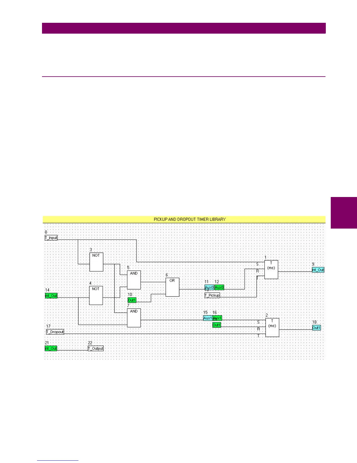
Open a new library or modify an existing one, in this example a timer library is going to be displayed Timer (Pkp-Dpt).lib as
shown on Figure 5–57:
Figure 5–57: TIMER (PKP-DPT).LIB CONFIGURATION EXAMPLE
Green and blue signals are internal inputs and outputs used in the library and are not going to be accessible to the user
when working in the main menu outside the library environment. The white boxes (T_Input, T_Pickup, T_Dropout,
T_output) are inputs and outputs to the library that are going to be accessible to the user to connect the library in the main
application to create virtual outputs to be sent to the relay.

Table of Contents

Other manuals for GE F650

Questions and Answers:

GE F650 Specifications

General IconGeneral
ModelF650
CategoryController
Frequency50/60 Hz
DisplayLCD
TypeFeeder Protection Relay
ApplicationFeeder Protection and Control
Communication ProtocolsDNP3, Modbus, IEC 61850
Protection FunctionsOvercurrent, Earth Fault
ManufacturerGeneral Electric
Input Voltage24-250 VDC/VAC

Summary

1 GETTING STARTED

1.1 IMPORTANT PROCEDURES

Covers essential procedures for safe and proper operation, including cautions, warnings, and safety instructions.

1.3 ENERVISTA 650 SETUP SOFTWARE

Details system requirements and installation procedures for the EnerVista 650 Setup software.

2 PRODUCT DESCRIPTION

2.3 ORDERING CODE

Details the structure of the ordering code for F650 units, specifying modules and options.

2.4 TECHNICAL SPECIFICATIONS

Outlines detailed technical specifications for protection elements, control, monitoring, and communications.

3 HARDWARE

3.2 POWER SUPPLY

Describes the power supply options (simple or redundant) and their characteristics.

3.4 WIRING

Provides details on external connections, digital inputs with trip circuit supervision, and cable/fiber Ethernet.

4 HUMAN INTERFACES. SETTINGS & ACTUAL VALUES

4.1 ENERVISTA 650 SETUP SOFTWARE INTERFACE

Describes the graphical user interface for configuring, monitoring, and troubleshooting the F650 relay.

4.2 HUMAN MACHINE INTERFACE (HMI)

Explains the HMI interface, including display options, keypad, front port, and communication.

5 SETTINGS

5.2 PRODUCT SETUP

Covers settings for serial ports, Ethernet, Modbus, DNP3, IEC protocols, and SNTP.

5.3 SYSTEM SETUP

Details system setup definitions including general settings, flex curves, breaker, switchgear, and time settings.

5.4 PROTECTION ELEMENTS

Lists and describes all protection elements, including current, voltage, power, and directional elements.

5.5 CONTROL ELEMENTS

Details control elements such as setting groups, frequency, synchrocheck, autoreclose, breaker failure, and load encroachment.

5.6 INPUTS/OUTPUTS

Covers input/output placement, contact I/O, virtual inputs, virtual outputs, remote comms, and analog inputs.

5.8 TESTING

Describes procedures for force IO-input and force IO-output testing.

5.9 RELAY CONFIGURATION

Explains how to configure outputs, LEDs, operations, protection elements, and oscillography.

5.10 LOGIC CONFIGURATION (PLC EDITOR)

Details logic configuration using graphical functions based on IEC 61131-3 standard.

5.11 IEC 61850 CONFIGURATION

Covers IEC 61850 configuration, including IED name, Ethernet parameters, and MMXU parameters.

5.12 PROCOME CONFIGURATION

Explains the configuration of PROCOME protocol for digital signals, measurements, and operations.

5.13 IEC 60870-5-103 PROTOCOL CONFIGURATION

Covers IEC 60870-5-103 protocol configuration for digital states, measurands, and commands.

6 ACTUAL VALUES

6.2 STATUS

Displays status signals for protection, control elements, breaker, protection summary, and system information.

7 IEC 61850 PROTOCOL

7.3 IEC 61850 CONFIGURATOR

Covers the IEC 61850 configuration tool for domain name, Ethernet parameters, and MMXU parameters.

8 SECURITY

8.1 ADDING USERS

Explains how to add new users and assign user rights through Administrator Access.

8.3 ENABLING SECURITY

Details how to enable security control in EnerVista 650 Setup by checking the 'ENABLE SECURITY' box.

9 BOOTCODE AND FIRMWARE UPGRADE

9.3 FIRMWARE VERSION UPGRADE

Provides step-by-step instructions for upgrading the F650 firmware version using EnerVista 650 Setup.

13 F650 TROUBLESHOOTING GUIDE

13.1 SYMPTOMS AND RECOMMENDED ACTIONS

Provides a troubleshooting guide listing common symptoms, possible causes, and recommended actions.

Related product manuals