5-140 F650 Digital Bay Controller GEK-106310AB
5.9 RELAY CONFIGURATION 5 SETTINGS
5
5.9.3 OPERATIONS
This menu option shows the settings for the 24 control operations that can be programmed, as follows:
• Select checkbox enables the desired operation.
• Command Text setting defines the command name.
• Interlocks Type setting defines the desired interlock type (An interlock is a condition that must be fulfilled for an
operation to be performed). The possible options are Logic or None. If the LOGIC option is selected, the program will
enable a new window for creating the logic. If the NONE option is selected, then the following setting (Interlocks) will
be irrelevant.
• Interlocks setting define the desired interlocks. This setting is enabled selecting the “logic” option in “Interlock type”.
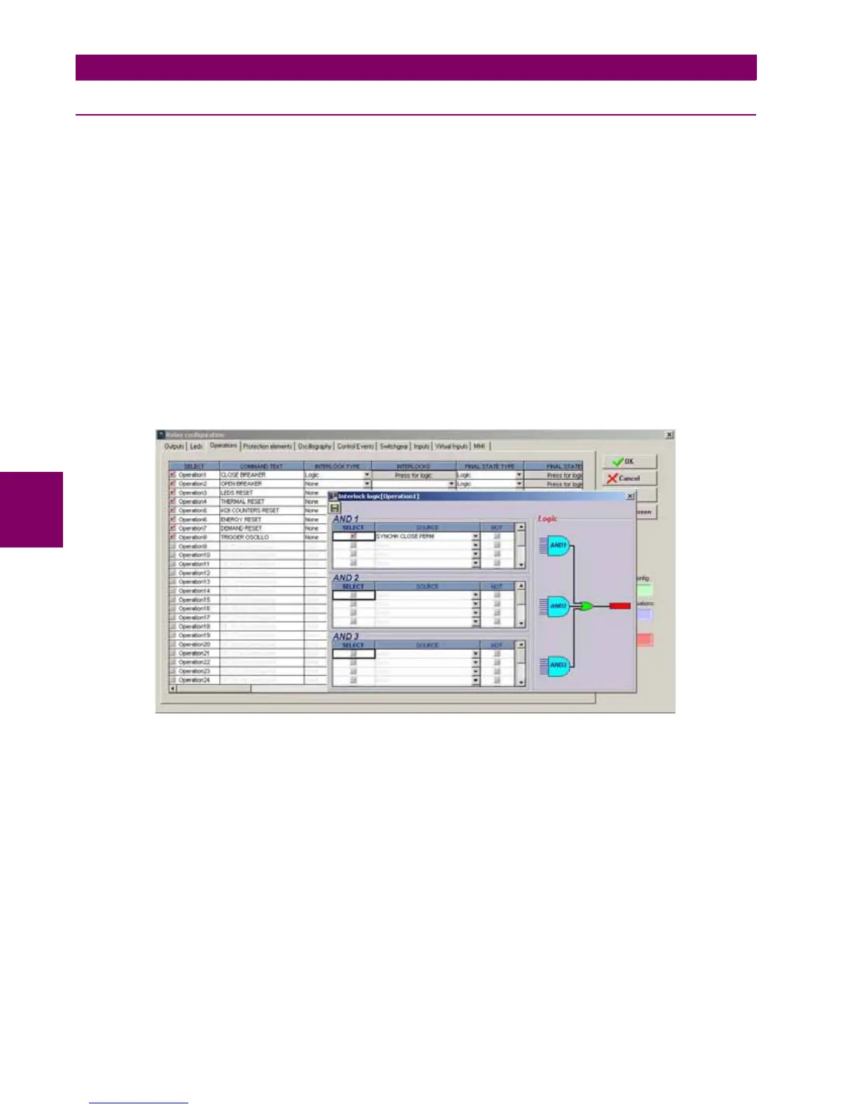
In the “Interlock logic” screen we can set the interlock logic, as shown on Figure 5–46:
The settings on this screen allow creating a logic configuration with up to 3 AND gates and 1 OR gate for each of the
24 operations available in the relay. These settings are:
Select – Enables/disables the selection for the interlock input
Source – Selects a function, digital input, logic, etc. for defining each input of each AND gate.
NOT – Logic inverter
Figure 5–46: OPERATIONS AND INTERLOCKS
• Final State Type setting: defines whether the operation requires (in addition to the interlock logic) any other conditions
to determine a “success condition”. If so, we must select LOGIC. Otherwise, we must select NONE.
• Final State setting: defines the success condition of a programmed operation, if the previous setting (Final State type)
was set as LOGIC.
• Front Key setting: defines the front pushbutton from which the operation can be executed.
• Contact Input setting: defines whether the operation can be executed by digital input. It defines the digital input to be
used for this purpose.
• Virtual Output setting: defines whether the operation can be executed from a virtual output previously defined at the
logic configuration tool (PLC logic).
• Time Out setting: defines the period during which the operation command will remain activated waiting for a success
condition. If the success signal is received before this period expires, the command signal will be removed and the
timer reset. If the success condition is not received within this period of time, the operation is considered to be finished.

 Loading...


