5-108 F650 Digital Bay Controller GEK-106310AB
5.5 CONTROL ELEMENTS 5 SETTINGS
5
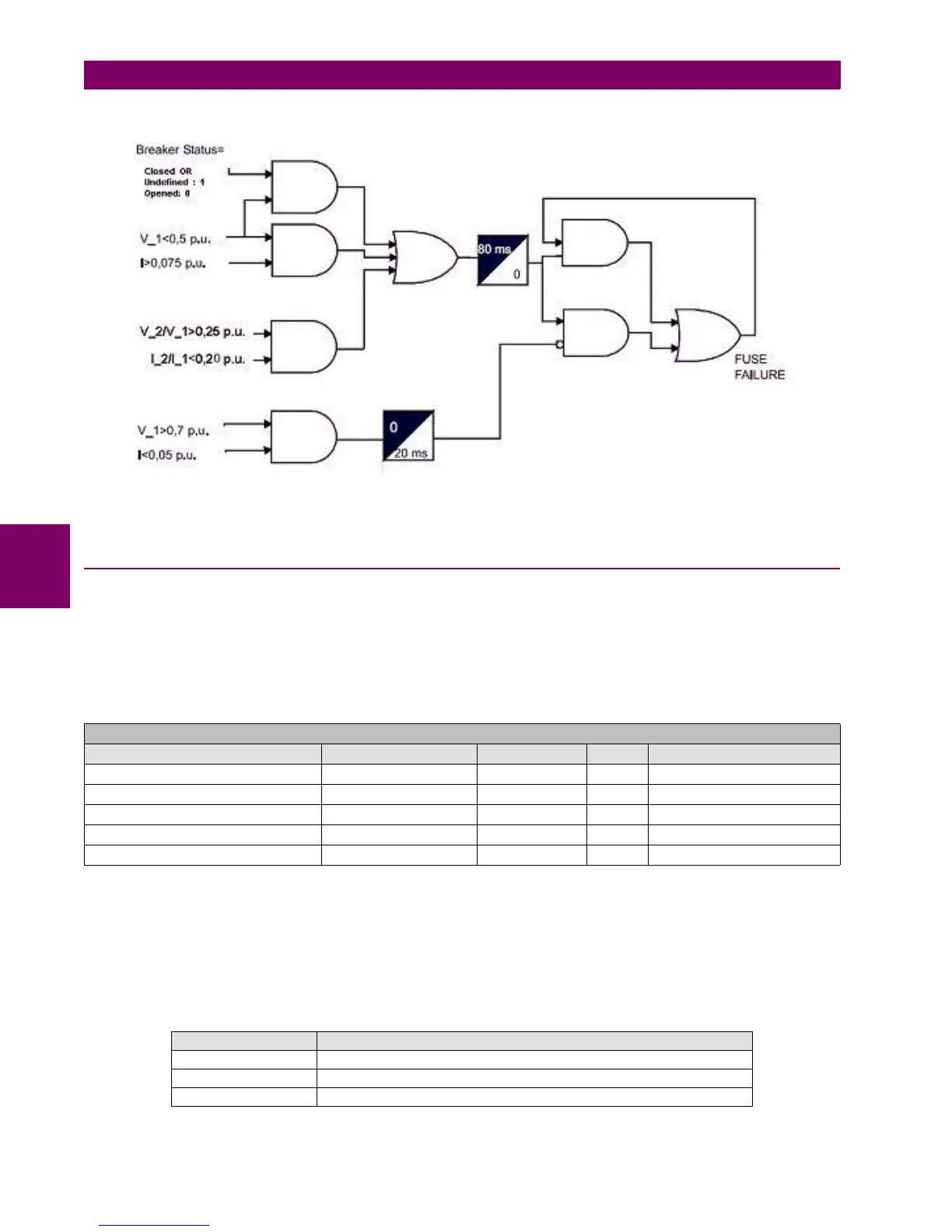
Figure 5–30: FUSE FAILURE ELEMENT BLOCK DIAGRAM
5.5.8 BROKEN CONDUCTOR
F650 incorporates a broken or fallen conductor detection function. The relay uses the ratio between the negative sequence
current, I
2
, and the positive sequence current I
1
. In normal and balanced load situations, this ratio is zero, while in severe
load fault conditions, an unbalance is produced and this ratio increases.
Setpoint > Control Elements > Broken Conductor
Table 5–86: BROKEN CONDUCTOR ELEMENT SETTINGS
This way, when the function is enabled and the unbalance is produced over the set percentage, the element will pick up. If
unbalance conditions are maintained during a period longer than the set time delay, the element will trip.
In order to avoid trips or pickups with very weak loads there is a current level threshold to inhibit the operation of the
element when the three phase currents are below a fixed level.
Note: The I2/I1 current inhibition level for the different firmware versions is as follows:
SETPOINT > CONTROL ELEMENTS > BROKEN CONDUCTOR
SETTING DESCRIPTION NAME DEFAULT VALUE STEP RANGE
Function permission Function DISABLED N/A [DISABLED – ENABLED]
Tap Level in percentage of I2/I1 Tap 20.0 0.1% [20.0 : 100.0]
Trip Time Trip Delay 60.00 0.01 s [0.00 : 900.00]
Snapshot event generation Snapshot Events ENABLED N/A [DISABLED – ENABLED]
Current Inhibition Level setting Operation Threshold 0.005 0.001 A [0.000 : 1.000]
FIRMWARE VERSION CURRENT INHIBITION LEVEL
1.50 or Lower 10 mA
1.60 or Higher 50 mA
1.80 or Higher Selectable by setting from 0.000 to 1.000 in steps of 0.001 A

 Loading...


