10-22 F650 Digital Bay Controller GEK-106310AB
10.15 OVERVOLTAGE ELEMENTS (59P, 59X, 59NH, 59NL, 47) 10 COMMISSIONING
10
10.15.3 59NH AND 59NL ELEMENTS
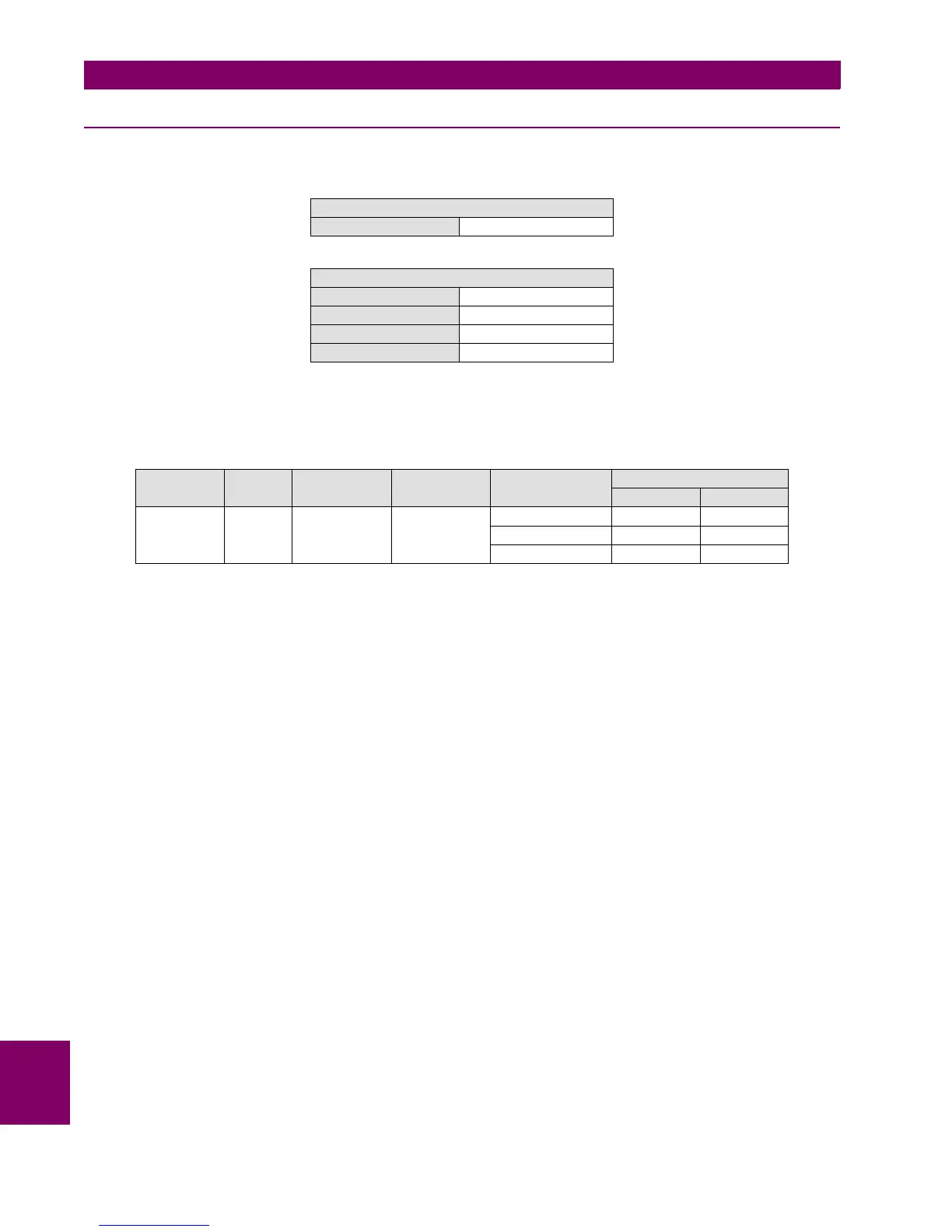
Set the relay as follows
Apply voltage as indicated on the table under the overvoltage setting level and verify that the relay does not trip.
Verify that the relay trips for the set voltage (with an admissible error of 5%).
This element can also be tested by applying only phase voltages. For this purpose, it is necessary to set Auxiliary Voltage =
VX. In this condition, Vn voltage is calculated as a sum of the phase voltages.
GENERAL SETTINGS
Auxiliary Voltage VN
NEUTRAL OV HIGH/LOW (59NH/59NL)
Function ENABLED
Pickup Level 120 V
Trip Delay 2.00
Reset Delay 0.00
ELEMENTS INPUT PICKUP LEVEL
(VOLTS)
TRIP DELAY
(SECONDS)
APPLIED
VOLTAGE (V)
TRIPPING TIME (S)
EXPECTED ADMISSIBLE
59NH/59NL VX 120 2 114 NO TRIP NA
132 2 [1.9–2.1 ]
132 2 [1.9 – 2.1]

 Loading...


