5-134 F650 Digital Bay Controller GEK-106310AB
5.6 INPUTS/OUTPUTS 5 SETTINGS
5
5.6.6 ANALOG BOARDS SPECIFIC SETTINGS
Hardware and software is provided to receive signals from external transducers and convert these signals into a digital
format for use as required. The relay will accept inputs in the range of –1 to +20 mA DC, suitable for use with the most
common transducer output ranges; all inputs are assumed to be linear over the complete range.
The Input Range setting specifies the mA DC range of the transducer connected to the input channel.
• Range: -1 to 0, 0 to 1, -1 to 1, 0 to 5, 0 to 10, 0 to 20, 4 to 20.
The Min and Max Value settings are used to program the span of the transducer in primary units.
• Min Value: -9999.99 to 9999.99
• Max Value: -9999.99 to 9999.99
5.6.7 VIRTUAL INPUTS
Virtual inputs are signals that can be written directly via communications. Their status can be established as ON (1) and
OFF (0), through writing by communications using EnerVista 650 Setup.
The change of state of virtual inputs is made according to their type. Latched virtual inputs remain at the set value until it is
changed by communications. Self-reset virtual inputs are activated by writing, and they remain active during one cycle.
There are 32 virtual inputs of each type.
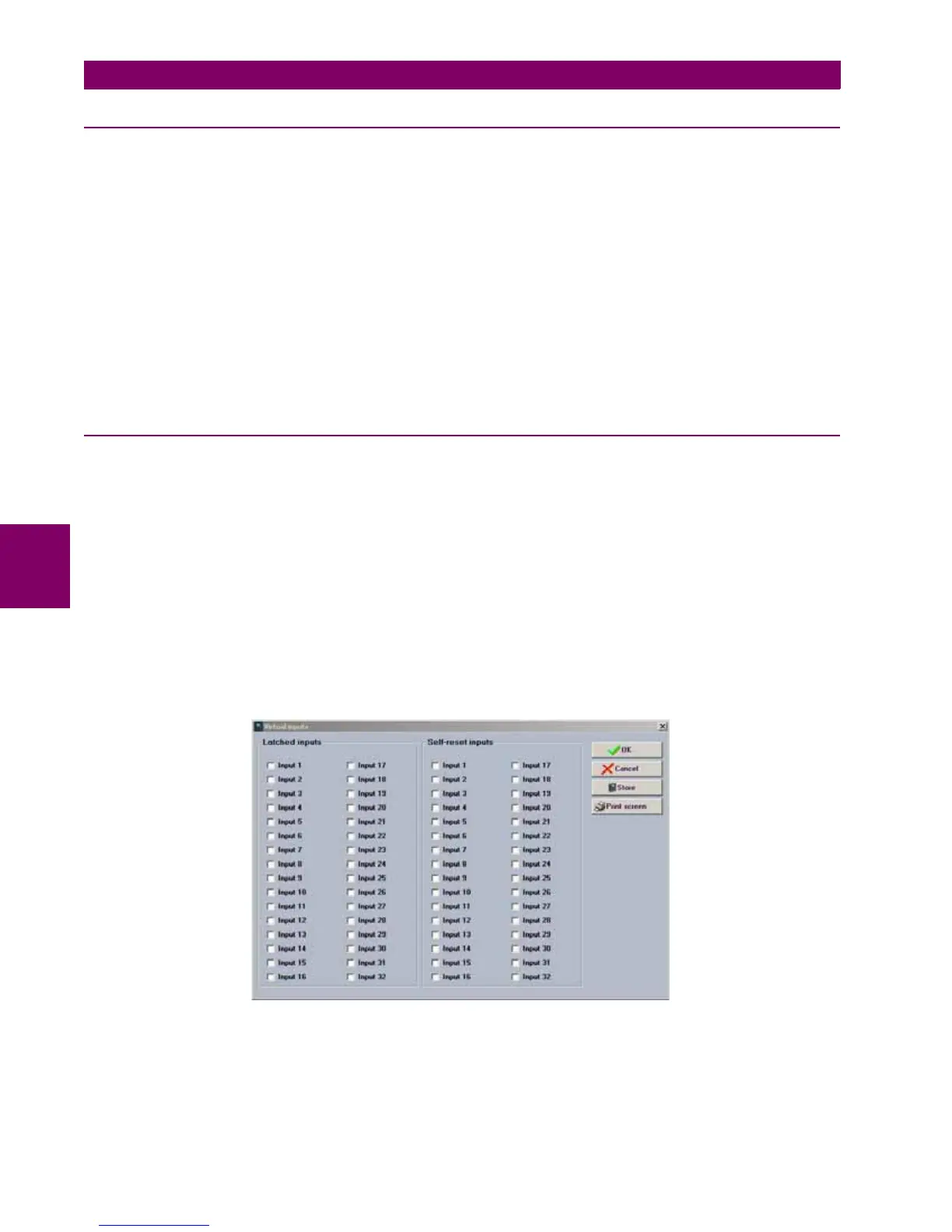
5.6.7.1 VIRTUAL INPUTS WRITING:
Setpoint > Input/Outputs >Virtual Inputs for activating / deactivating signals
To write a virtual input, select the virtual input to activate clicking on the virtual input checkbox, then press on the store
button and virtual input will be written to the relay (see Figure 5–42:).
If it is a self-reset one it will remain active during one PLC cycle and after that the virtual input value will be cleared.
If it is a latched one, the value will remain active until it is cleared by the user, clicking again in the virtual input
checkbox and pressing on store to clear the value.
Figure 5–42: VIRTUAL INPUTS WRITING THROUGH ENERVISTA 650 SETUP

 Loading...


