5-112 F650 Digital Bay Controller GEK-106310AB
5.5 CONTROL ELEMENTS 5 SETTINGS
5
5.5.11 ANALOG COMPARATORS
The F650 provides 20 different analog comparators in an analog comparator module located in the control elements part of
the device. Each analog comparator gives indication when the analog variable selected is inside or outside some minimum
and maximum threshold values.
The settings can be selected at Setpoint > Control Elements > Analog Comparators
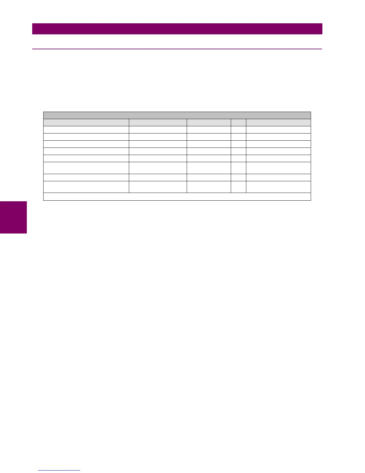
Table 5–92: ANALOG COMPARATORS SETTINGS
The analog comparator settings includes two global settings such as
Analog Function: This setting allows enabling or disabling the analog comparators module. Each analog comparator can
not be enabled/disabled individually.
Analog Snapshot Events: The snapshot event setting enables or disables the snapshot event generation for this element.
Besides the main settings there are some settings for each analog comparator (up to 20) as follows:
Analog Input: Analog value selected by the user from the available analog variables in the device. This will be used to
make the comparison inside a set band for that magnitude.
Analog Maximum: Maximum threshold value for the comparison band.
Analog Minimum: Minimum threshold value for the comparison band.
Analog Delay: Time value for the analog signal to be active inside the comparison band before setting the Analog Level
signal to 1.
Analog Hysteresis: It establishes the deadband at each extreme when going out of operation band.
Direction IN: min value = min - hysteresis (in %)
max value = max + hysteresis (in %)
Direction OUT
: min value = min + hysteresis (in %)
max value = max - hysteresis (in %)
Analog Direction: Analog direction for the activation signal to be set Inside or Outside the Deadband.
OUT:The "Analog Level X" will give an activation signal when the analog value is located outside the comparison
band.
IN:The "Analog Level X" will give an activation signal when the analog value is located inside the comparison band.
The F650 provides 20 different analog comparators. Their status values can be viewed at Actual> Status > Control
Elements > Analog Comparators:
SETPOINT > CONTROL ELEMENTS > ANALOG COMPARATORS
SETTING DESCRIPTION NAME DEFAULT VALUE STEP RANGE
Generic Analog Function Permission Analog Function DISABLED N/A [DISABLED – ENABLED]
Generic Snapshot Events Generation Analog Snapshot Events DISABLED N/A [DISABLED – ENABLED]
Analog Input Value Selection Analog Input X None N/A [All available analog values]
Analog Maximum Threshold Value Analog Maximum X 1.000 0.001 [-100000.000 : 100000.000]
Analog Minimum Threshold Value Analog Minimum X 1.000 0.001 [-100000.000 : 100000.000]
Analog Delay for Activation Signal Analog Delay X 0.00 0.01
s
[0.00 : 900.00]
Analog Hysteresis for the Deadband Analog Hysteresis X 1.0 0.1 [0.0 : 50.0]
Analog Direction for Activation Inside or
Outside the Deadband
Analog Direction X Out N/A [IN-OUT]
Note: X is the analog comparator index, up to 20

 Loading...


