GEK-106310AB F650 Digital Bay Controller 11-3
11 APPLICATION EXAMPLES 11.1 EXAMPLE 1: COMMUNICATION & PROTECTION SETTINGS PROCEDURE
11
11.1.3 PROCEDURE TO SET THE PROTECTION FUNCTION
Once the relay has been connected set protection functions and outputs according to the following steps:
Open EnerVista 650 SETUP program and under:
SETPOINT SYSTEM SETUP GENERAL SETTINGS
Under
SETPOINT PROTECTION ELEMENTS PHASE CURRENT PHASE TOC HIGH PHASE TOC HIGH 1
Under
SETPOINT CONTROL ELEMENTS INPUTS/OUTPUTS BOARD F
Under
SETPOINT RELAY CONFIGURATION OUTPUTS
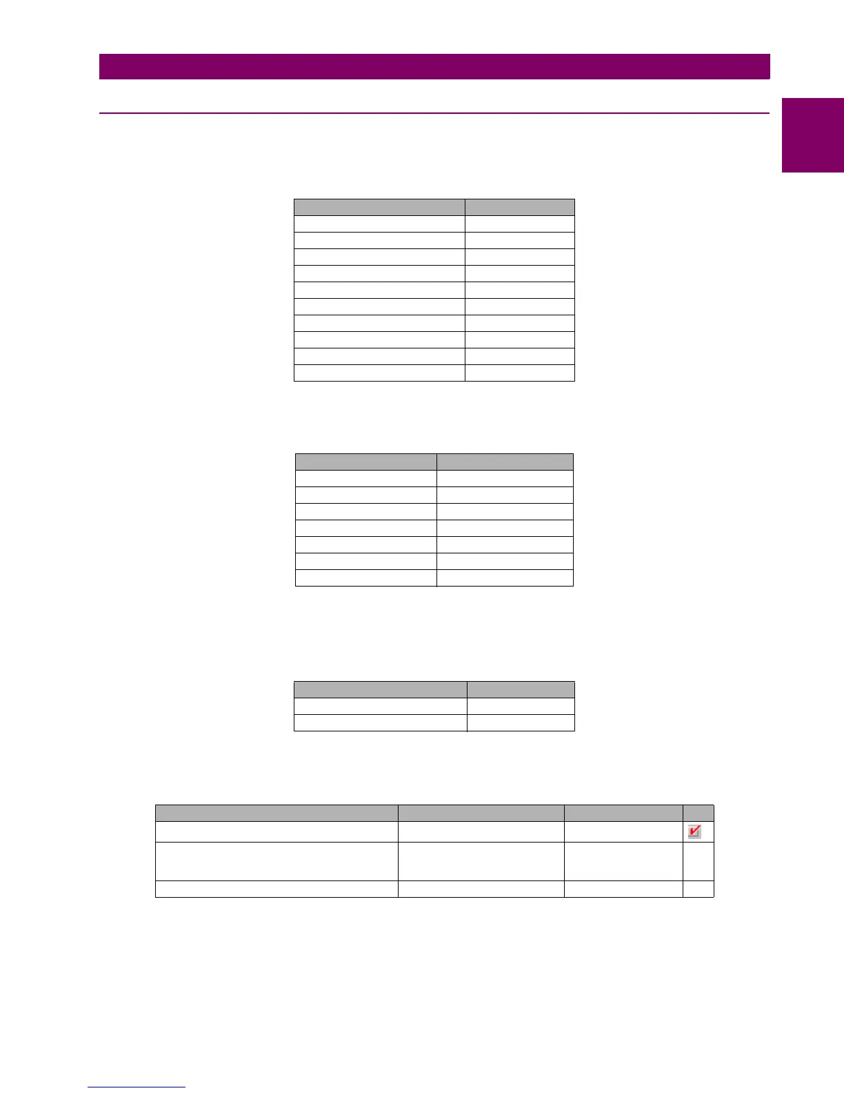
NAME VALUE
Phase CT Ratio 1.0 (default)
Ground CT Ratio 1.0 (default)
Stv Ground CT Ratio 1.0 (default)
Phase VT Ratio 1.0 (default)
Phase VT Connection Wye
Nominal Voltage 100.0 (default)
Nominal Frequency 50
Phase Rotation ABC
Frequency Reference VI (default)
Auxiliary Voltage VX (default)
NAME VALUE
Function Enabled
Input Phasor DFT
Pickup Level 5.0 A
Curve IEC Curve A
TD Multiplier 0.1
Reset Instantaneous
Voltage Restraint Disabled
NAME VALUE
Output Logic_00_00 Positive
Output Type_00_00 Latch
SELECT NAME SOURCE OR
Contact Output Operate 00 (Board F) C Output Oper_00_00 PRESS FOR LOGIC
Phase TOC A Op
Phase TOC B Op
Phase TOC C Op
Contact Output Reset 00 (Board F) C Output Reset_00_00 Operation bit 000

 Loading...


