CHAPTER 4: SETPOINTS PROTECTION
869 MOTOR PROTECTION SYSTEM – INSTRUCTION MANUAL 4–105
Motor Elements
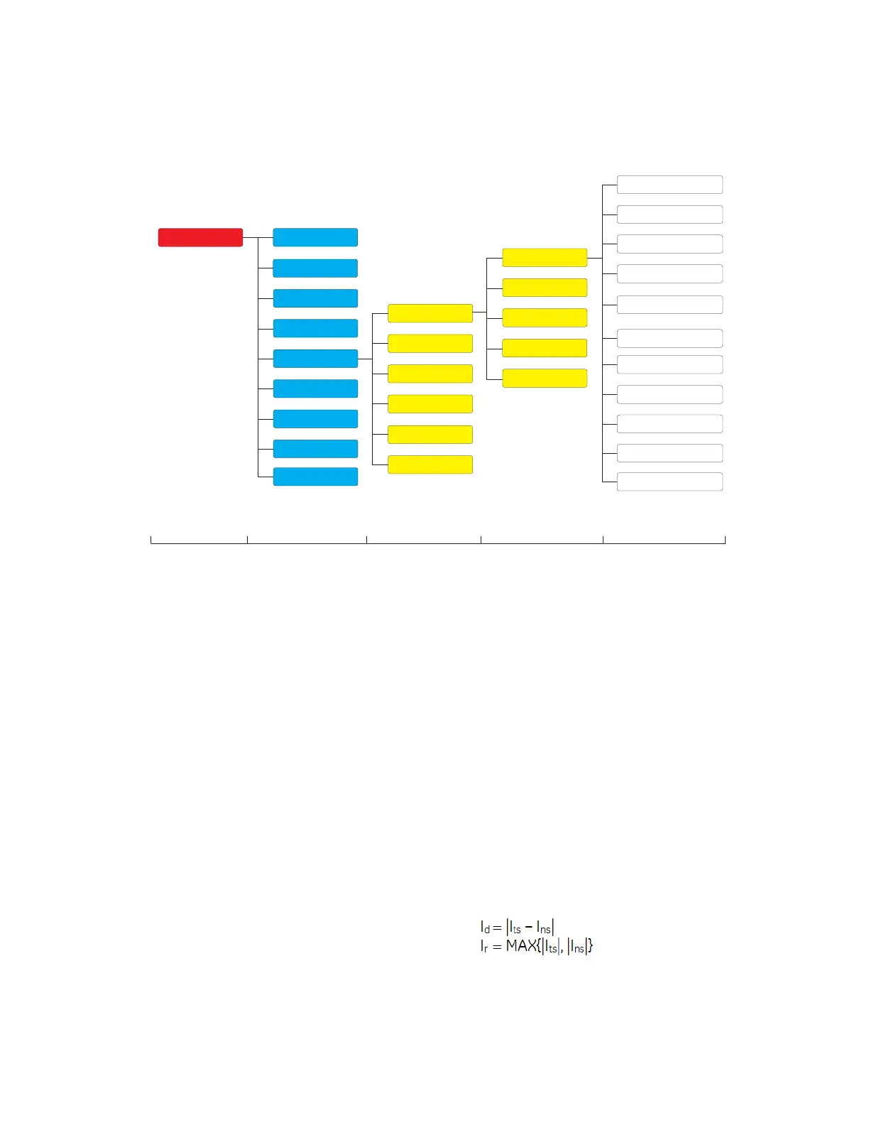
Figure 4-28: Motor Elements Display Hierarchy
Percent Differential
The 869 relay provides one Percent Differential element per protection group using an
internal summation method (described below). It is intended for use on the stator windings
of the rotating machinery. This element is available only if the second AC analog input card
with the K1-CT bank is properly installed in slot K. Two methods are available, depending
upon the power wiring option used: Internal Summation percent differential and Core
Balance percent differential. For wiring options, please refer to Installation/Electrical
Installation/Differential CT Inputs chapter of the manual.
For internal summation percent differential, it is recommended that the terminal side CTs
and neutra
l side CTs have the same ratios but it is allowed for the ratios to be different. The
maximum allowable ratio mismatch is 10:1. In the case of a mismatch, the 869 scales the
curr
ents to the primary of the CT with the higher primary value which is used as the CT
reference for the percent differential element.
Internal summation and core balance percent differential both operate in per phase basis
(
phase-segregated). The key variables used in the element are the Restraining current (I
r
)
and the Differential current (I
d
). The way they are calculated depends on the used
differential method as follows:
Internal Summation Method
For internal summation method, differential current Id and restraint current I
r
are defined
below:
Eq. 2
Setpoints
Device
System
Inputs
Outputs
Protection
Monitoring
Control
FlexLogic
Data Capture
Group 1
Thermal Model
Level 1 Level 2 Level 3 Level 4 Level 5
Data Capture
Power
Frequency
Voltage
Current
Group 2
Group 3
Group 4
Group 5
Group 6
Motor
Current Unbalance
Mechanical Jam
Undercurrent
Overload Alarm
Short Circuit
Percent Differential
Ground Fault
Acceleration Time
Underpower
Testing
Loss of Excitation

 Loading...


