4–234 869 MOTOR PROTECTION SYSTEM – INSTRUCTION MANUAL
PROTECTION CHAPTER 4: SETPOINTS
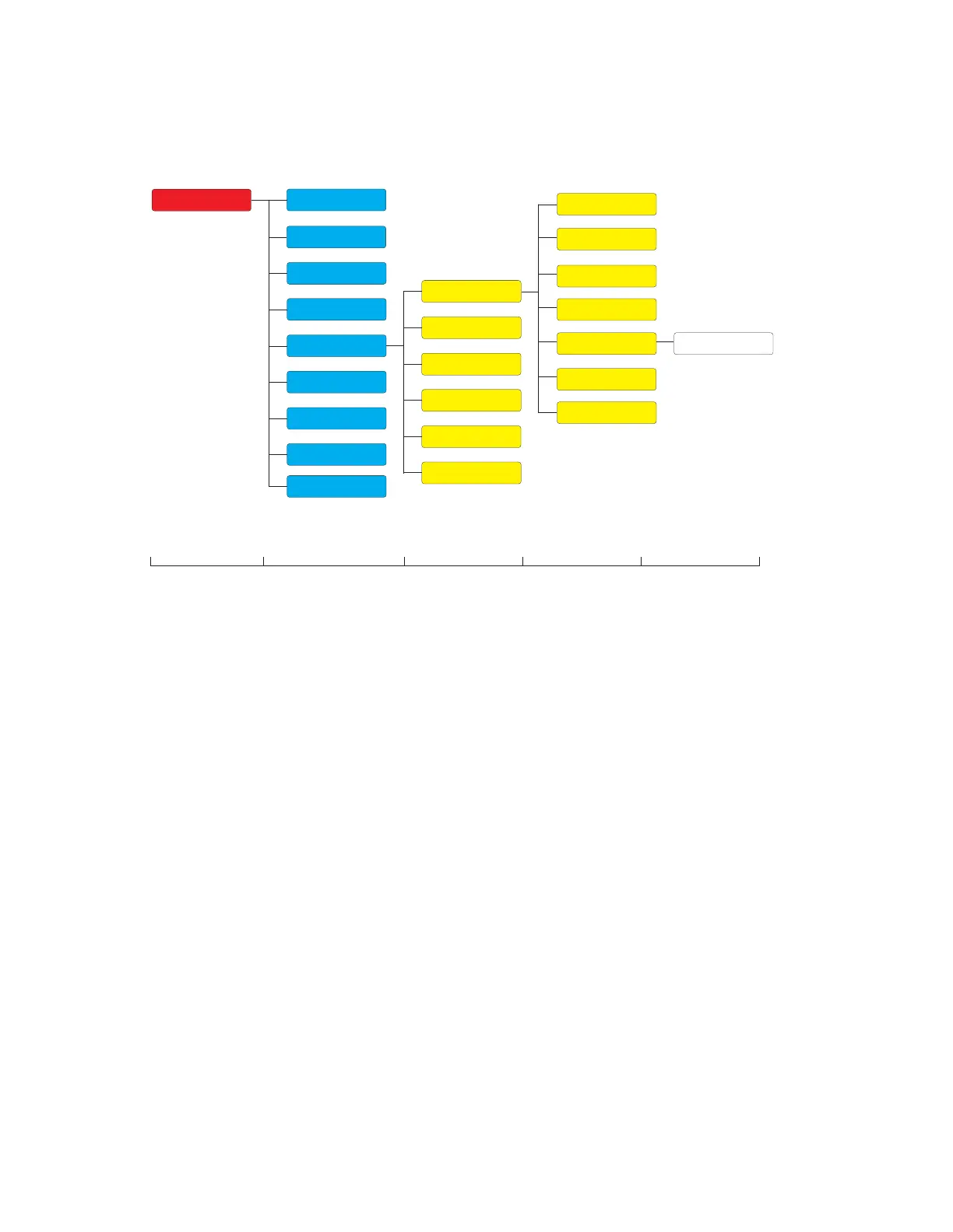
Impedance Elements
Figure 4-84: Impedance Elements Display Hierarchy
Out-of-step
The Out-of-step element provides an out-of-step (loss-of-synchronism or pole slip) tripping
function for motors. The element measures the positive-sequence apparent impedance,
and traces its locus with respect to a single blinder operating characteristic with an offset
mho supervisory. The purpose of the supervisory mho is to permit tripping for swings that
pass through the motor and a limited portion of the system, but to prevent operation on
stable swings that pass through both blinders and outside the mho characteristic.
The out-of-step tripping feature operates as follows: The trip sequence identifies unstable
power swi
ngs by determining whether the impedance locus enters one blinder, spends a
finite time between the left and right blinder characteristics, and then exits the opposite
blinder. The out-of-step trip process is supervised by a mho characteristic. If the locus
enters the left blinder, right blinder and mho characteristic (indicated by the AND operation
of OOS LFT BLD PKP and OOS RGT BLD PKP FlexLogic operands) for an interval longer than
PICKUP DELAY, the timing out signal (OOS TIMER PKP FlexLogic operand) is established.
After the PICKUP DELAY timer times out, latch 1 is set as long as the impedance stays
within the mho characteristic. If afterwards, at any time (given the impedance stays
between the two blinders characteristic), the locus exits from the opposite blinder, latch 2
is set as long as the impedance stays inside the mho characteristic. The element is now
ready to trip. If the "BLINDER EXIT" trip mode is selected, the OOS OP operand is set
immediately and sealed-in for the interval set by the SEAL-IN DELAY. If the "MHO EXIT" trip
mode is selected, the element waits until the impedance locus leaves the mho
characteristic, and then the OOS OP operand is set and sealed-in.
Setpoints
Device
System
Inputs
Outputs
Protection
Monitoring
Control
FlexLogic
Data Capture
Level 1 Level 2 Level 3 Level 4
Data Capture
Power
Frequency
Impedance
Current
Group 1
Group 2
Group 3
Group 4
Group 5
Group 6
Motor
2-Speed Motor
Testing
Level 5
Data CaptureVoltage
Out-of-step

 Loading...


