CHAPTER 4: SETPOINTS MONITORING
869 MOTOR PROTECTION SYSTEM – INSTRUCTION MANUAL 4–267
Breaker Arcing
Current
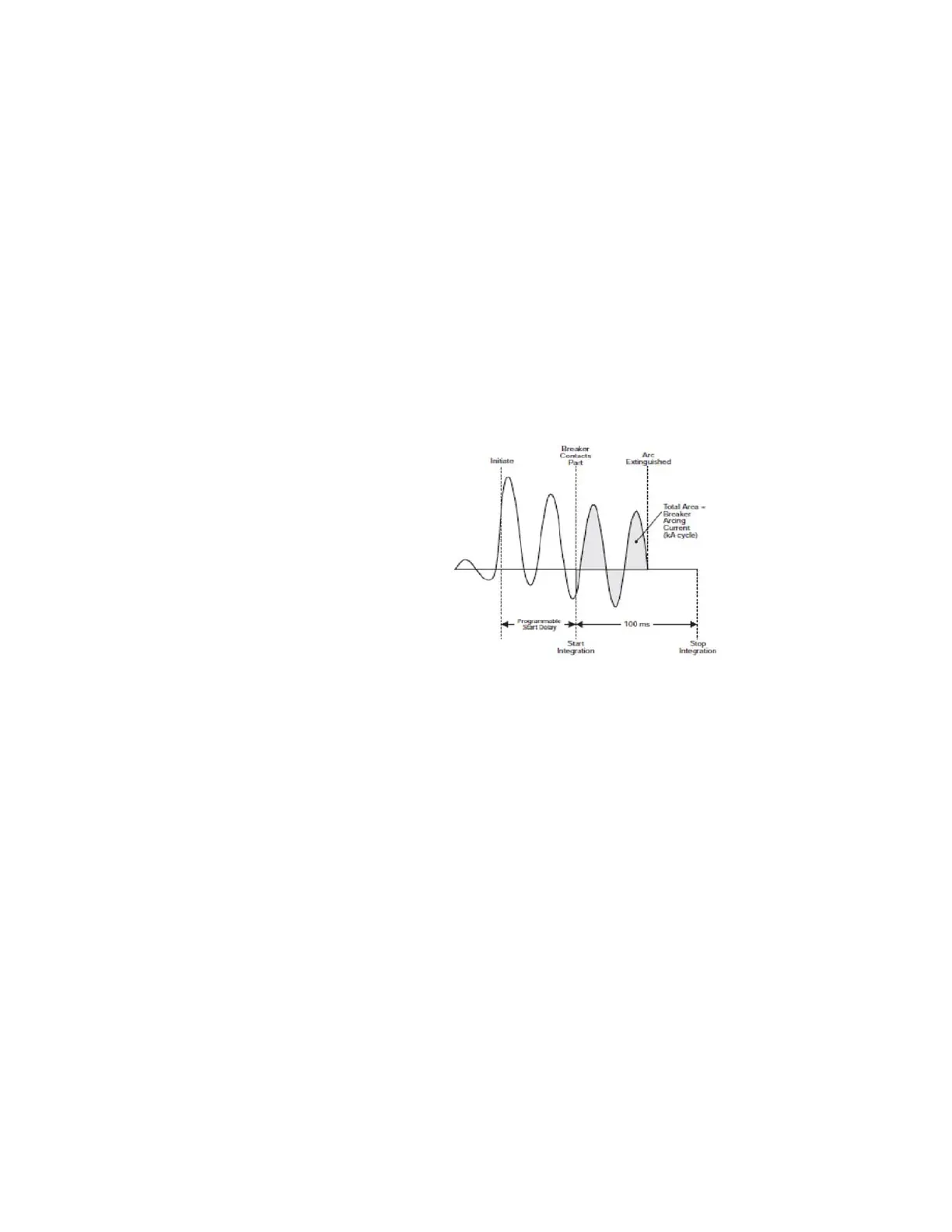
The 869 relay provides one Breaker Arcing Current element.This element calculates an
estimate of the per-phase wear on the breaker contacts by measuring and integrating the
current squared passing through the breaker contacts as an arc. These per-phase values
are added to accumulated totals for each phase and compared to a programmed
threshold value. When the threshold is exceeded in any phase, the relay can set an output
operand and set an alarm. The accumulated value for each phase can be displayed as an
actual value.
The same output operands that are selected to operate the Trip output relay that is used to
trip the br
eaker indicating a tripping sequence has begun, are used to initiate this feature.
A time delay is introduced between initiation and starting of integration to prevent
integration of current flow through the breaker before the contacts have parted. This
interval includes the operating time of the output relay, any other auxiliary relays and the
breaker mechanism. For maximum measurement accuracy, the interval between the
change-of-state of the operand (from 0 to 1) and contact separation should be measured
for the specific installation. Integration of the measured current continues for 100 ms,
which is expected to include the total arcing period.
Figure 4-104: Breaker Arcing Current Measurement
Path:
Setpoints > Monitoring > BKR 1 Arcing Current
FUNCTION
Range: Disabled, Alarm, Latched Alarm, Configurable
Default: Disabled
INITIATION
Range: Off, Any operand from the list of FlexLogic operands
Default: Off
The setpoint selects the FlexLogic operand, digital input, virtual input or remote input
that initiates the Breaker Arcing Current scheme, typically the Trip signals from internal
protection functions.
DELAY
Range: 0.000 to 6000.00 s in steps of 0.001 s
Default: 0.030 s
The setpoint provides a delay interval between the time the tripping sequence is initiated
and the time the breaker contacts are expected to part, starting the integration of the
measured current.

 Loading...


