4–134 869 MOTOR PROTECTION SYSTEM – INSTRUCTION MANUAL
PROTECTION CHAPTER 4: SETPOINTS
Current Unbalance
Unbalance current, also known as negative sequence current or I
2
, results in
disproportionate rotor heating. If the thermal overload protection’s unbalance bias feature
has been enabled (by setting non-zero value for the Unbalance Bias K Factor under
Setpoints > Protection > Group 1(6) > Motor > Thermal Model
, the thermal overload
protection protects the motor against unbalance by tripping when the motor’s thermal
capacity is exhausted. However, the current unbalance protection can detect this
condition and alarm and /or trip before the motor has heated substantially. For the
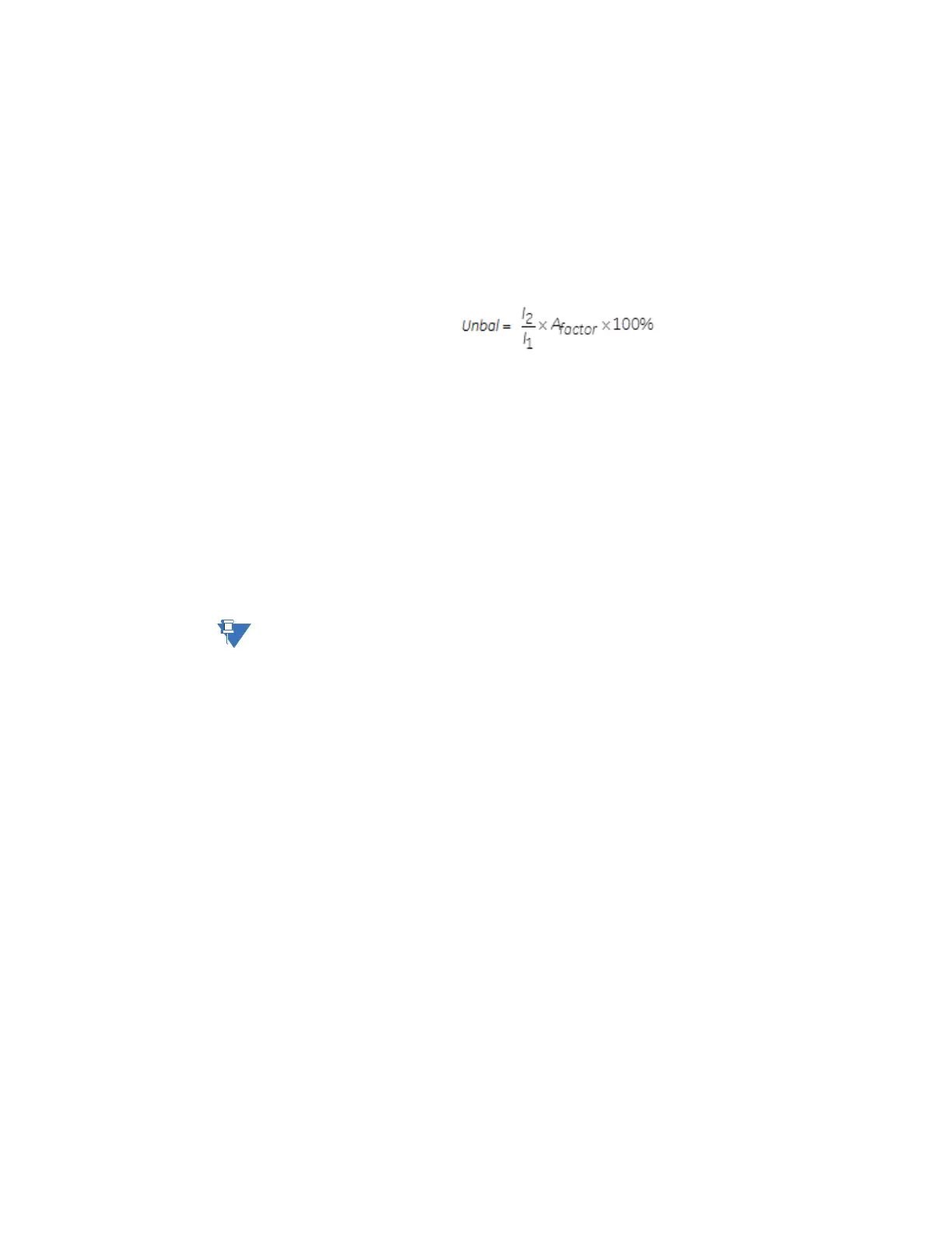
869 relay, unbalance is defined as the ratio of negative-sequence to positive-sequence
curr
ent,
Eq. 26
where A
factor
is the adjustment factor used to prevent nuisance trip and/or alarm at light
loads.
If the motor is operating at an average current level (I
avg
) equal to or greater than the
programmed full load current (FLA, as selected by the
Setpoints > System > Motor > Setup
),
the adjustment factor (A
factor
) is one. However, if the motor is operating at an average
current level (I
avg
) less than FLA then the adjustment factor (A
factor
) is the ratio of average
current to full load current.
If this element is enabled, a trip and/or alarm occur(s) once
the unbalance level equals or
exceeds the set pickup for the set period of time. If the unbalance level exceeds 40% (30%
when VFD Function is enabled and VFD is not bypassed), or when I
avg
≥ 25% FLA and
current in any one phase is less than the cutoff current, the motor is considered to be
single phasing and a trip occurs within 2 seconds. Single phasing protection is disabled if
the unbalance trip feature is “Disabled”.
NOTE:
Unusually high unbalance levels can be caused by incorrect phase CT wiring.
Path:
Setpoints > Protection > Group 1(6) > Motor > Current Unbalance
TRIP FUNCTION
Range: Disabled, Trip, Configurable
Default: Disabled
This setting enables the Current Unbalance Trip functionality.
TRIP PICKUP
Range: 4.0 to 50.0% in steps of 0.1%
Default: 15%
The setting specifies a pickup threshold for the trip function. When setting the pickup
level, note that a 1% voltage unbalance typically translates into a 6% current unbalance.
To prevent nuisance trips or alarms, the pickup level must not be set too low. Also, since
short term unbalances are common, a reasonable delay must be set to avoid nuisance
trips or alarms. This setting must be greater than the corresponding setting for the alarm
stage.

 Loading...


