CHAPTER 4: SETPOINTS PROTECTION
869 MOTOR PROTECTION SYSTEM – INSTRUCTION MANUAL 4–195
Neutral Directional
Overcurrent
Protection
The 869 Neutral Directional Overcurrent protection element provides both forward and
reverse fault direction indications: the Ntrl Dir OC FWD and Ntrl Dir OC REV, respectively.
The output operands are asserted if the magnitude of the operating current is above a
Pickup level (overcurrent unit) and the fault direction is seen as forward or reverse,
respectively (directional unit).
The ov
ercurrent unit responds to the magnitude of a fundamental frequency phasor of
the neutral current calculated from the phase currents. There are separate Pickup settings
for the forward-looking and reverse-looking functions. The element applies a positive-
sequence restraint for better performance; a small user-programmable portion of the
positive-sequence current magnitude is subtracted from the zero sequence current
magnitude when forming the operating quantity.
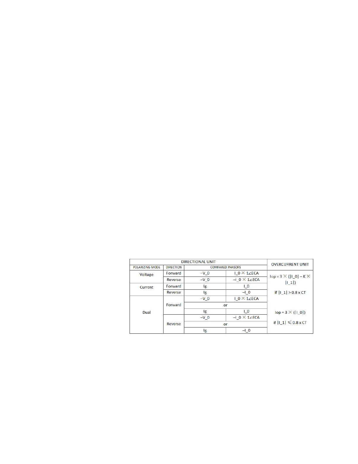
Iop = 3 * (|I_0| - K * |I_1|)
The positive-sequence restraint allows for more sensitive settings by counterbalancing
spurious
zero-sequence currents resulting from:
• system unbalances under heavy load conditions
• current transformer (CT) transformation errors of during double-line and three-phase
fault
s
• switch-off transients during double-line and three-phase faults.
The positive-sequence restraint must be considered when testing for Pickup accuracy and
r
esponse time (multiple of Pickup). The operating quantity depends on the way the test
currents are injected into the relay (single-phase injection: Iop = (1 – K) × Iinjected ; three-
phase pure zero-sequence injection: Iop = 3 × Iinjected).
The positive-sequence restraint is removed for low currents. If the positive-sequence
curr
ent is below 0.8 x CT, the restraint is removed by changing the constant K to zero. This
facilitates better response to high-resistance faults when the unbalance is very small and
there is no danger of excessive CT errors as the current is low.
The di
rectional unit uses the zero-sequence current (I_0) for fault direction discrimination
and may be programmed to use either zero-sequence voltage (“Calculated V0” or
“Measured VX”), ground current (Ig), or both for polarizing. The following tables define the
neutral directional overcurrent element.
Where:
V_0 = 1/3 * (Vag + Vbg + Vcg) = zero sequence voltage
I
_0 = 1/3 * In = 1/3 * (Ia + Ib + Ic) = zero sequence current
ECA = element characteristic angle
In = neutral current
When POLARIZING VOLTAGE is set to “Measured VX,” one-third of this voltage is used in
pla
ce of V_0. The following figure explains the usage of the voltage polarized directional
unit of the element by showing the voltage-polarized phase angle comparator
characteristics for a phase A to ground fault, with:
ECA = 90° (element characteristic angle = centerline of operating characteristic)
FWD L
A = 80° (forward limit angle = the ± angular limit with the ECA for operation

 Loading...


